Engine - complete dismantling
OHV engines 1 The need for dismantling will have been dictated by wear or noise in most cases.
Although there is no reason why only partial dismantling cannot be carried out to renew such items as the timing chain or crankshaft rear oil seal, when the main bearings or bigend bearings have been knocking and especially if the vehicle has covered a high mileage, then it is recommended that a complete strip down is carried out and every engine component examined (Section 13).
2 Position the engine so that it is upright on a bench or other convenient working surface. If the exterior is very dirty it should be cleaned before dismantling using paraffin and a stiff brush or a water-soluble solvent.
3 Remove the coolant pipe from the side of the engine by disconnecting the hose clips and the securing bolt.
4 If not already done, drain the engine oil.
5 Remove the dipstick and unscrew and discard the oil filter.
6 Disconnect the HT leads from the spark plugs, release the distributor cap and lift it away complete with leads.
7 Unscrew and remove the spark plugs.
8 Disconnect the breather hose from the inlet manifold and remove it with the oil filler cap.
9 Disconnect the fuel and vacuum pipes from the carburettor and unbolt and remove the carburettor (refer to Chapter 4, Part A).
10 Unbolt the thermostat housing cover and remove it together with the thermostat (refer to Chapter 3).
11 Remove the rocker cover.
12 Remove the rocker shaft assembly (four bolts).
13 Withdraw the pushrods, keeping them in their originally fitted order (see illustration).
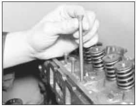
12.13 Keep the pushrods in strict order after removal
14 Remove the cylinder head complete with manifolds as described in Section 4.
15 Remove the distributor as described in Chapter 5, Part B.
16 Unbolt and remove the fuel pump.
17 Remove the oil pump (Section 10).
18 Pinch the two runs of the water pump drivebelt together at the pump pulley to prevent the pulley rotating and release the pulley bolts.
19 Release the alternator mounting and adjuster link bolts, push the alternator in towards the engine and remove the drivebelt.
20 Unbolt the alternator bracket and remove the alternator.
21 Unbolt and remove the water pump.
22 Unscrew the crankshaft pulley bolt. To do this, the flywheel starter ring gear will have to be jammed to prevent the crankshaft from turning.
23 Remove the crankshaft pulley. If this does not pull off by hand, carefully use two levers behind it placed at opposite points.
24 Place the engine on its side and remove the sump. Do not invert the engine at this stage, or sludge and swarf may enter the oilways.
25 Unbolt and remove the timing chain cover.
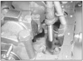
26 Take off the oil slinger from the front face of the crankshaft sprocket.
27 Slide the chain tensioner arm from its pivot pin on the front main bearing cap.
28 Unbolt and remove the chain tensioner (see illustration).
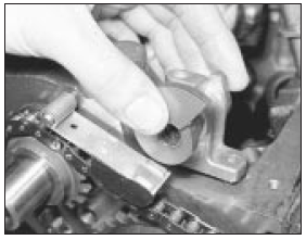
12.28 Removing the timing chain tensioner
29 Bend back the lockplate tabs from the camshaft sprocket bolts and unscrew and remove the bolts.
30 Withdraw the sprocket complete with timing chain.
31 Unbolt and remove the camshaft thrust plate (see illustration).
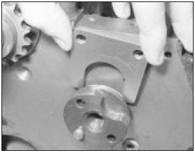
12.31 Camshaft thrust plate removal
32 Rotate the camshaft until each cam follower (tappet) has been pushed fully into its hole by its cam lobe.
33 Withdraw the camshaft, taking care not to damage the camshaft bearings (see illustration).
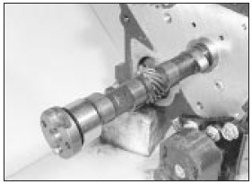
12.33 Withdrawing the camshaft from the front of the engine
34 Withdraw each of the cam followers, keeping them in their originally fitted sequence by marking them with a piece of numbered tape or using a box with divisions (see illustration).
12.34 Using a valve grinding tool suction cup to withdraw the cam followers
35 From the front end of the crankshaft, draw off the sprocket using a two-legged extractor.
36 Check that the main bearing caps are marked F (Front), C (Centre) and R (Rear). The caps are also marked with an arrow which indicates the timing cover end of the engine, a point to remember when refitting the caps.
37 Check that the big-end caps and connecting rods have adjacent matching numbers facing towards the camshaft side of the engine. Number 1 assembly is nearest the timing chain end of the engine. If any markings are missing or indistinct, make some of your own with quick-drying paint (see illustration).
12.37 Connecting rod and big-end cap markings
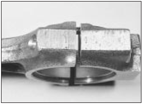
38 Unbolt and remove the big-end bearing caps. If the bearing shell is to be used again, tape the shell to the cap.
39 Now check the top of the cylinder bore for a wear ring. If one can be felt, it should be removed with a scraper before the piston/rod is pushed out of the cylinder.
40 Remove the piston/rod by pushing it out of the top of the block. Tape the bearing shell to the connecting rod.
41 Remove the remaining three piston/rod assemblies in a similar way.
42 Unbolt the clutch pressure plate cover from the flywheel. Unscrew the bolts evenly and progressively until spring pressure is relieved, before removing the bolts. Be prepared to catch the clutch friction plate as the cover is withdrawn.
43 Unbolt and remove the flywheel. It is heavy, do not drop it. If necessary, the starter ring gear can be jammed to prevent the flywheel rotating. There is no need to mark the fitted position of the flywheel to its mounting flange as it can only be fitted one way. Take off the adapter plate (engine backplate).
44 Unbolt and remove the crankshaft rear oil seal retainer.
45 Unbolt the main bearing caps. Remove the caps, tapping them off if necessary with a plastic-faced hammer. Retain the bearing shells with their respective caps if the shells are to be used again, although unless the engine is of low mileage this is not recommended (see Section 13). To improve access to the No 2 main bearing bolt on 1.3 litre engines the oil pick-up tube can be removed by drifting it out. A new pick-up tube must be obtained for reassembly together with suitable adhesive to secure it in position.
46 Lift the crankshaft from the crankcase and lift out the upper bearing shells, noting the thrustwashers either side of the centre bearing. Keep these shells with their respective caps, identifying them for refitting to the crankcase if they are to be used again.
47 With the engine now completely dismantled, each component should be examined as described in Section 13 before reassembling.
HCS engines
48 The procedure is as described previously
in this Section for OHV engines, noting the
following differences.
a) There is no coolant transfer pipe along the front of the engine.
b) Disconnect and remove the HT leads with reference to Chapter 5, Part B.
c) There is no distributor to remove. The procedure for removal of the DIS coil is given in Chapter 5, Part B.
d) big-end cap bolts are Torx type bolts.
e) Remove the engine speed sensor as described in Chapter 5, Part B before removing the flywheel to prevent damage to the sensor.
f) There are three main bearings on 1.1 engines and five on 1.3 engines. From the timing chain end, the main bearing caps are numbered 1 to 3 or 1 to 5 as applicable, and have an arrow on them which must point towards the timing chain end of the engine.
g) The crankshaft thrust bearings are still fitted either side of the centre main bearing.
h) rear oil seal carrier is secured in place by Torx type bolts.
See also:
Turbocharger - general description
Escort RS Turbo models are equipped with
an exhaust driven turbocharger, which is a
device designed to increase the engine’s
power output without increasing exhaust
emissions or adversely affectin ...
Rear brake shoe lining check (Every 6000 miles or 6 months)
1 Due to the fact that the rear brake drums
are combined with the hubs, which makes
removal of the drums more complicated than
is the case with detachable drums, inspection
of the shoe linings can ...
Boot lid (Saloon models) - removal and refitting
Removal
1 Open the boot lid, and place protective
covers (old rags or cardboard) beneath the
corners of the lid, and over the rear wings to
prevent damage to the paintwork.
2 Where applicable, di ...
