General information
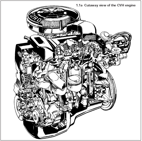
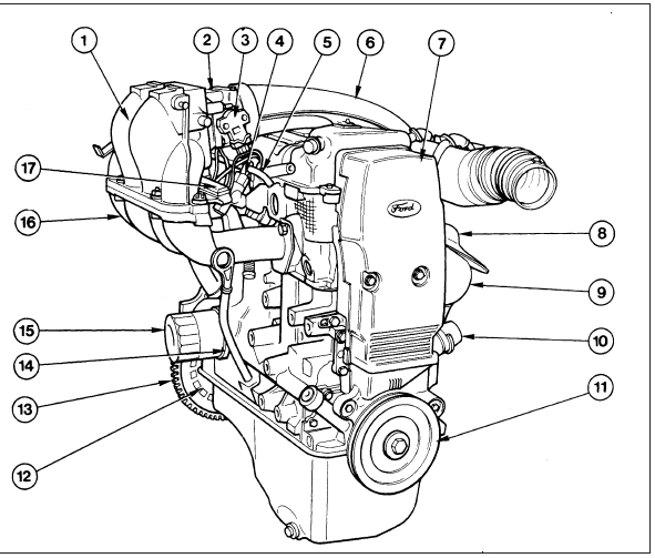
The 1.1 litre, 1.3 litre, 1.4 litre and 1.6 litre CVH (Compound Valve angle, Hemispherical combustion chambers) engines are of four cylinder in-line overhead camshaft type, mounted transversely, together with the transmission, at the front of the car (see illustrations).

1.1a Cutaway view of the CVH engine

1.1b 1.6 litre EFI engine
1 Inlet manifold (upper)
2 Throttle housing
3 Throttle position sensor
4 Fuel rail
5 Fuel hose
6 Air inlet duct
7 Timing belt cover
8 Exhaust heat shield
9 Exhaust manifold
10 Coolant inlet pipe
11 Crankshaft pulley
12 Flywheel ribs
13 Flywheel
14 Oil cooler
15 Oil filter
16 Inlet manifold (lower)
17 Fuel injection wiring harness
The crankshaft is supported in five main bearings within a cast iron crankcase.
The cylinder head is of light alloy construction, supporting the overhead camshaft in five bearings. Camshaft drive is by a toothed composite rubber belt, driven from a sprocket on the crankshaft.
The distributor (where applicable) is driven from the rear (flywheel) end of the camshaft by means of an offset dog.
The cam followers are of hydraulic type, which eliminates the need for valve clearance adjustment. If the engine has been standing idle for a period of time, or after overhaul, when the engine is started up, valve clatter may be heard. This is a normal condition and will gradually disappear within a few minutes of starting up as the cam followers are pressurised with oil.
The water pump is mounted on the timing belt end of the cylinder block and is driven by the toothed belt.
A gear or rotor type oil pump is mounted on the timing belt end of the cylinder block and is driven by a gear on the front end of the crankshaft.
A full-flow oil filter of throw-away type is located on the side of the crankcase.
An engine oil cooler is located under the oil filter on fuel-injection and automatic transmission models.
See also:
Rear disc splash shield - removal and refitting
Note: A suitable puller will be required to
remove the drive flange, and a new rear hub
nut must be used on reassembly.
Caution: Refer to the
precautions in Section 1.
Removal
1 Loosen the rear ...
Doors - removal and refitting
Front door
Pre-1986 models
Removal
1 Open the door fully and support its lower
edge on a jack or blocks covered with a pad
of cloth to prevent scratching.
2 Unscrew the two bolts which hold the
...
Front wheel alignment - checking and adjusting
1 Front wheel alignment is defined by
camber, castor steering axis inclination and
toe setting. The first three factors are
determined in production; only toe can be
adjusted in service. Incorrect ...
