Temperature gauge sender unit - removal and refitting
Note: Suitable jointing compound will be required on refitting.
Removal
1 With the engine cold unscrew the pressure
cap on the thermostat housing or expansion
tank as applicable, then refit it. This will
release any residual pressure in the system
and minimise coolant loss when the sender
unit is removed.
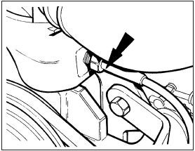
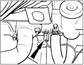
2 Disconnect the wiring and unscrew the sender unit located on the forward facing side of the cylinder head, below the thermostat housing on OHV engines, or adjacent to the thermostat housing on CVH engines (see illustrations).

7.2a Temperature gauge sender unit location in cylinder head - OHV engines

7.2b Temperature gauge sender unit location in cylinder head - CVH engines
Refitting 3 To refit, smear the threads of the sender unit with jointing compound and screw it into the cylinder head securely.
4 Reconnect the wiring and top-up the cooling system as described in Chapter 1.
See also:
Spark control system components (carburettor models) - removal and refitting
Spark delay and sustain valves
1 Disconnect the vacuum pipes at the valve
and withdraw the valve.
2 When refitting a spark delay valve, the valve
must be positioned with the black end
(marked “CA ...
Automatic transmission fluid level check (Every 12 000 miles (20 000 km) or
12 months)
1 Fluid level should be checked with the
transmission at operating temperature (after a
run) and with the vehicle parked on level
ground.
2 Open and prop the bonnet. With the engine
idling and th ...
Vacuum servo unit and linkage - removal and refitting
Removal
1 Refer to Section 12 and remove the master
cylinder.
2 On fuel-injection models unclip and lift out
the front section of the heater plenum
chamber to provide access to the connecting
li ...
