Fuel injector - removal and refitting
Note: Refer to the precautions at the end of Section 1 before proceeding. New injector seals will be required on refitting.
Removal
1 Disconnect the battery negative lead.
2 Remove the air cleaner assembly.
3 Depressurise the fuel system as described in Section 6.
4 Disconnect the fuel injector wiring plug (see illustration).
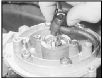
10.4 Disconnecting the fuel injector wiring plug - 1.4 CFI engine
5 Bend back the injector retaining collar securing bolt locktabs, then unscrew the bolts. Remove the injector retaining collar (see illustrations).
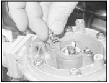
10.5a Removing an injector retaining collar securing bolt and locktab - 1.4
CFI engine
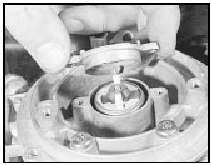
10.5b Removing the injector retaining collar - 1.4 CFI engine
6 Withdraw the injector from the CFI unit, noting its orientation, then withdraw the injector seals (see illustration).
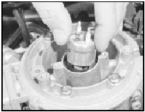
10.6 Withdrawing the injector from the CFI unit
7 Remove the seal from the injector retaining collar (see illustration).
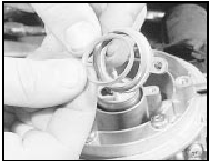
10.7 Removing the seal from the injector retaining collar - 1.4 CFI engine
Refitting 8 Refitting is a reversal of removal, bearing in mind the following points.
9 Use new injector seals, and coat them with silicon grease (to Ford specification ESEM- 1C171A or equivalent).
10 Ensure that the locating peg on the injector is correctly positioned (see illustration).
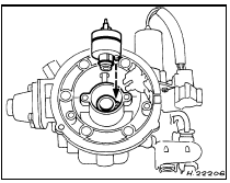
10.10 Align locating peg on injector with slot in CFI unit when refitting
See also:
Exhaust manifold - removal and refitting
2.0 litre SOHC models
1 Refer to Chapter 4 Part A, Section 26, but
note the following points.
2 Ignore the references to removal and
refitting of the air cleaner and hot air pick-up
pipe, and not ...
Jump starting your vehicle
The gases around the battery can explode if exposed to flames,
sparks, or lit cigarettes. An explosion could result in injury or
vehicle damage.
Batteries contain sulfuric acid which can burn ski ...
Engine coolant renewal (Every 36 000 miles (60 000 km) or 3 years)
Caution: Before proceeding,
note the precautions given in
Chapter 3, Section 1.
1 Disconnect the battery negative lead.
2 It is preferable to drain the cooling system
with the engine cold. If thi ...
