
Front brake disc - inspection, removal and refitting
Note: Before starting work, refer to the warning at the beginning of Section 2 concerning the dangers of asbestos dust.
Inspection
1 Fully apply the handbrake then loosen the
front roadwheel bolts. Raise and support the
front of the vehicle on safety stands (see
“Jacking and Vehicle Support”) and remove
the roadwheel(s).
2 Examine the surface of the disc. If it is deeply grooved or scored or if any small cracks are evident, it must either be refinished or renewed. Any refinishing must not reduce the thickness of the disc to below a certain minimum (see “Specifications”). Light scoring on a brake disc is normal and should be ignored.
3 If disc distortion is suspected, the disc can be checked for run-out using a dial gauge or feeler blades located between its face and a fixed point as the disc is rotated (see illustration).
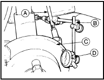
4.3 Checking brake disc run-out
A Steering tie-rod
B Dial gauge
support fixture
C Brake disc
D Dial gauge
4 Where the run-out exceeds the specified figure, renew the disc.
Removal
5 With the roadwheel removed (see paragraph
1), proceed as follows.
6 To remove a disc, unbolt the caliper anchor bracket, withdraw it and tie it up to the suspension strut to avoid strain on the flexible hose (if necessary, remove the brake pads as described in Section 2) (see illustration).
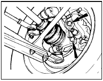
4.6 Caliper anchor bracket-to-hub carrier retaining bolts (arrowed)
7 Extract the small disc retaining screw and pull the disc from the hub (see illustration).
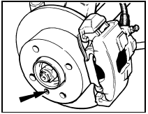
4.7 Brake disc retaining screw location (arrowed)
Refitting 8 If a new disc is being installed, clean its surface free from preservative.
9 Fit the disc and tighten the retaining screw.
10 Refit the caliper anchor bracket (and where applicable the brake pads - see Section 2), and the roadwheel and lower the vehicle to the floor.
See also:
Rear hub bearings - adjustment
Note: A new hub nut split-pin must be used
on refitting.
1 Raise and support the rear of the vehicle on
stands. Release the handbrake.
2 This adjustment will normally only be
required if, when th ...
Engine oil cooler - removal and refitting
Note: Suitable sealant will be required on
refitting - see text.
Removal
1 Remove the engine oil filter (Chapter 1).
2 Note the angle at which the coolant hoses
are set, then disconnect the hoses ...
Interior pillar trim panels - removal and refitting
Front pillar
1 Remove the two trim panel securing screws
and withdraw the panel (see illustration)..
41.1 Interior pillar trim panel fixings - Hatchback models
A Front pillar trim panel
B1 Cent ...
