Hydraulic system - bleeding (anti-lock braking system)
Note: Before starting work, refer to the warning at the beginning of Section 11 concerning the dangers of hydraulic fluid.
1 On cars equipped with the anti-lock braking system there are two bleed procedures possible according to which part of the hydraulic system has been disconnected.
2 If any one of the following conditions are
present, bleed procedure A should be
adopted:
a) A modulator has been removed.
b A modulator-to-master cylinder return hose has been drained.
c) The two modulator hydraulic hoses have been removed.
3 If any one of the following conditions are
present, bleed procedure B should be
adopted:
a) Any condition where the master cylinder
has been drained providing that the
modulator fluid return pipe has not lost its
head of fluid.
b) Removal of any of the basic braking system components ie brake caliper, flexible hose or pipe, wheel cylinder, load apportioning valve.
Bleed procedure A
4 Top-up the master cylinder reservoir to the
“MAX” mark using the specified type of fluid
and keep it topped up throughout the bleed
procedure.
5 Using a Torx type key or socket bit slacken the bypass valve on the relevant modulator by one to one and a half turns. The bypass valve is located between the two flexible hoses on the side of the modulator (see illustration).
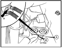
23.5 Modulator bypass valve (A) location
6 Fully depress and hold depressed the auto bleed plunger on the modulator so that the plunger circlip contacts the modulator body (see illustration).
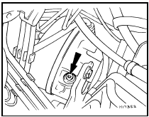
23.6 Modulator auto bleed plunger location (arrowed)
7 Have an assistant steadily pump the brake pedal at least twenty times while you observe the fluid returning to the master cylinder reservoir. Continue this operation until the returning fluid is free from air bubbles.
8 Release the auto bleed plunger ensuring that it has fully returned. Pull it out by hand if necessary.
9 Tighten the bypass valve on the modulator.
10 Now carry out bleed procedure B.
Bleed procedure B
11 This procedure is the same as for
conventional braking systems and reference
should be made to Section 11. Note,
however, that all the weight of the car must be
on the roadwheels, not suspended wheel free,
otherwise the load apportioning valves will not
bleed.
See also:
Fuel injectors - removal and refitting
Caution: Refer to the
precautions in Section 1 before
proceeding.
Note: A tachometer and an exhaust gas
analyser will be required to check the idle
mixture on completion. New seals and
retaining ...
Diagram 2: 1980-86 Lighting all models
Diagram 2: 1980-86 Lighting all models ...
Road test (Every 12 000 miles or 12 months)
Instruments and electrical
equipment
1 Check the operation of all instruments and
electrical equipment.
2 Make sure that all instruments read
correctly, and switch on all electrical
equipment in ...
