Sunroof - removal, refitting and adjustment
Glass panel - removal and
refitting
1 Open the sunblind and remove the three
screws and clips shown (see illustration)
then slide the lower frame rearwards into the
roof.
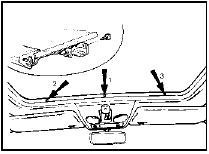
39.1 Sunroof lower frame-to-glass panel securing screws and clips (arrowed)
Tighten screws in the order shown when refitting
2 Remove the six screws securing the glass panel to the sliding gear (see illustration) then push the glass panel upwards and remove it from outside of the vehicle, taking care not to damage the paintwork.
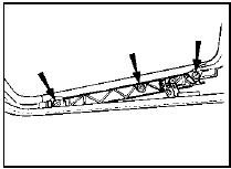
39.2 Sunroof glass panel-to-sliding gear securing screws (one side shown for
clarity)
3 Commence refitting by securing the glass panel to the sliding gear with the six screws.
4 Adjust the sunroof as described in paragraphs 10 and 12 to 14 inclusive, but note that there is no need to open and close the roof before checking adjustment.
5 Refit the three clips to the glass panel, then pull the lower frame forwards and secure it to the glass panel with the three screws. Tighten the screws in the order shown.
Complete assembly - removal and
refitting
6 Fully open the sliding roof panel, then
remove the screw securing the roof operating
handle and detach the handle.
7 Remove the four screws on each side and the two screws at the front securing the sliding roof assembly to the roof tray.
8 Lift the front rail and carefully withdraw the assembly forwards from the roof tray, taking care not to damage the paintwork.
9 Refitting is a reversal of removal, but on completion, adjust the sunroof as described in paragraph 10 onwards, and if necessary adjust the position of the roof operating handle so that with the roof in its closed position, the handle can fold into its recess.
Adjustment
10 Fully open and close the sliding roof, then
check that the front edge of the glass panel is
flush with, or a maximum of 2.0 mm (0.08 in)
below the adjacent roof panel. The rear edge
of the glass panel should be flush with, or a
maximum of 2.0 mm (0.08 in) above the
adjacent roof panel.
11 If adjustment is necessary, remove the three screws securing the glass panel to the lower frame, then slide the lower frame rearwards into the roof.
12 To adjust the front edge of the glass panel, loosen the front and centre screws securing the glass panel to the sliding gear.
13 To adjust the rear edge of the glass panel, loosen the rear and centre screws securing the glass panel to the sliding gear (see illustration 39.1).
14 On completion of adjustment, tighten the glass panel-to-sliding gear securing screws.
15 Pull the lower frame forwards and secure it to the glass panel with the three screws.
Tighten the screws in the order shown.
Interior trim panels - general information
1 The method of removal and refitting for most interior trim panels is self-explanatory.
The panels are fixed in place either by screws, which may be concealed by plastic blanking plugs in some cases, or by clips on the rear of the panel.
2 When removing a panel secured by clips, prise the panel as close as possible to each clip, using a forked tool similar to that shown (see illustration, 17.6b) or a wide-bladed screwdriver to prevent damage to the panel.
3 Refer to the relevant Sections of this Chapter for removal and refitting details of the major trim panels.
See also:
Ford VV carburettor - removal and refitting
Note: Refer to the warning at the end of
Section 1 before proceeding. A new gasket
must be used on refitting.
Removal
1 Disconnect the battery negative lead.
2 Remove the air cleaner (Section 2). ...
Rear stub axle carrier Saloon and Estate models) - removal and
refitting
Removal
1 Raise and support the rear of the car on
stands (see “Jacking and Vehicle Support”).
Remove the roadwheel.
2 Remove the rear hub as described in
Section 9.
3 Remove the rear brake shoe ...
Rear wheel cylinder (drum brakes) - removal, overhaul and refitting
Caution: Refer to the
precautions in Section 1.
Saloon, Hatchback and Estate
models
1 Chock the front wheels, loosen the relevant
roadwheel nuts, then jack up the rear of the
vehicle and support ...
