Front hub bearings - renewal
Note: A new driveshaft nut, and a new tie-rod balljoint split-pin must be used on refitting.
1 Remove the wheel trim and release the staking on the driveshaft retaining nut using a suitable punch.
2 Slacken the driveshaft retaining nut and the wheel bolts.
3 Jack up the front of the car, support it on stands (see “Jacking and Vehicle Support”) and remove the roadwheel.
4 Undo the two bolts securing the brake caliper anchor bracket to the hub carrier.
5 Withdraw the anchor bracket and brake caliper complete with disc pads and suspend it from a convenient place under the wheel arch.
6 Remove the driveshaft retaining nut and washer.
7 Undo the retaining screw and withdraw the brake disc from the hub.
8 Using a two-legged puller draw off the hub (see illustration).
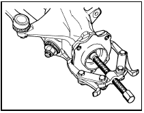
2.8 Using a two-legged puller to draw off the wheel hub
9 Extract the split pin and unscrew the castellated nut from the steering tie-rod balljoint.
10 Release the balljoint from the steering arm using a balljoint separator tool.
11 Disconnect the lower arm balljoint from the hub carrier by removing the nut and pinch-bolt (see illustration). Note that the pinch-bolt is of the socket-headed (Torx) type and a special key or socket bit (available from accessory shops) will be required for this purpose.
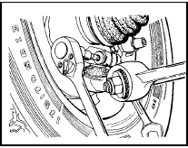
2.11 Removing the lower arm balljoint Torx type pinch-bolt
12 Undo the bolt which secures the hub carrier to the base of the suspension strut.
13 Using a suitable lever, separate the carrier from the strut by prising open the clamp jaws (see illustration).
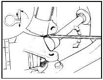
2.13 Using a lever to spread the hub carrier clamp jaws
14 Support the driveshaft so that it does not hang down by more than 20° from the horizontal then withdraw the hub carrier.
15 Support the hub carrier in a vice fitted with protected jaws.
16 Using pliers, pull out the dust shield from the groove in the hub carrier.
17 Prise out the inner and outer oil seals.
18 Lift out the bearings.
19 With a suitable drift, drive out the bearing tracks. Take care not to damage the bearing track carrier surface during removal since any burrs on the surface could prevent the new tracks seating correctly during assembly.
20 Clean away all old grease from the hub carrier.
21 Drive the new bearing tracks squarely into their seats using a piece of suitable diameter tubing.
22 Liberally pack a high quality lithium based grease into the bearings, making sure to work plenty into the spaces between the rollers.
Note that the cavity between the inner and outer bearings in the carrier must not be packed with grease since this could cause a pressure build-up and result in the seals leaking.
23 Install the bearing to one side of the carrier, then fill the lips of the new oil seal with grease and tap it squarely into position (see illustration).
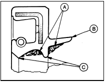
2.23 Sectional view of the hub bearing oil seal
A Grease applied to cavity between oil seal lips
B Axial sealing lip
C Radial sealing lips
24 Fit the bearing and its seal to the opposite side in a similar way.
25 Fit the dust shield by tapping it into position using a block of wood.
26 Smear the driveshaft splines with grease, then install the carrier over the end of the driveshaft.
27 Connect the carrier to the suspension strut and tighten the bolt to the specified torque.
28 Reconnect the suspension lower arm balljoint to the carrier and secure by passing the pinch-bolt through the groove in the balljoint stud. The head of the pinch-bolt should be to the rear.
29 Reconnect the tie-rod to the steering arm, tighten the castellated nut to the specified torque and secure with a new split pin.
30 Install the hub/disc and push it on to the driveshaft as far as it will go using hand pressure only.
31 The threaded end of the driveshaft joint should be protruding far enough through the hub to enable it to be drawn fully home using the old driveshaft nut and packing washers. If this is not the case it will be necessary to use Ford special tool 14-022 or a suitable alternative (see illustration).
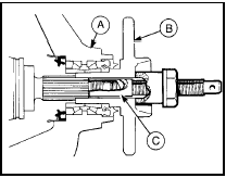
2.31 Using special tool 14-022 to fit the front hub and driveshaft
A Hub carrier
B Hub
C Tool 14-022
32 With the hub in place fit a new driveshaft retaining nut and the washer but only tighten the nut hand tight at this stage.
33 Refit the brake disc and caliper anchor bracket, tightening the anchor bracket bolts to the specified torque.
34 Refit the roadwheel and lower the car to the ground.
35 Tighten the driveshaft retaining nut to the specified torque then stake the nut into the driveshaft groove using a small punch (see illustration).
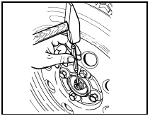
2.35 Staking the driveshaft retaining nut
36 Tighten the wheel bolts to the specified torque and refit the wheel trim.
See also:
Crankshaft and main bearings - removal and refitting
1.8 litre (R2A type)
Removal
1 With the engine removed from the vehicle,
remove the timing belt, crankshaft sprocket
and thrustwasher.
2 Remove the pistons and connecting rods. If
no work is to ...
Front tie-bar - removal and refitting
Pre-May 1983 1.1 litre models
Removal
1 Jack up the front of the car and support it
on stands (see “Jacking and Vehicle Support”).
2 Unscrew and remove the nut which holds
the tie-bar to the larg ...
Rocker gear - dismantling and reassembly
Dismantling
1 With the rocker assembly removed as
described in Section 4, extract the split pin
from one end of the rocker shaft (see
illustration).
6.1 Rocker shaft assembly components
2 Take ...
