Fuel computer components - removal and refitting
Computer unit
Removal
1 Disconnect the battery negative terminal.
2 Undo the two instrument panel bezel retaining screws and ease the bezel out to release the lower clips.
3 Withdraw the computer module from the facia to the right of the instrument panel.
4 Disconnect the wiring multi-plug and remove the computer.
Refitting
5 Refitting is a reversal of removal.
Speed sender unit
Removal
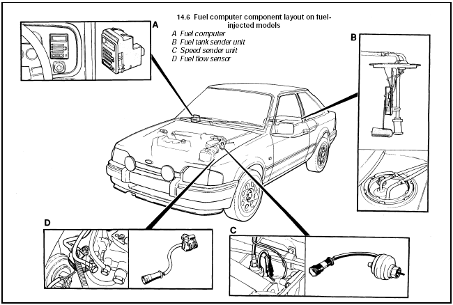
6 Undo the retaining nut and detach the
speedometer cable from the speed sender
unit (see illustration).

14.6 Fuel computer component layout on fuelinjected models
A Fuel computer
B Fuel tank sender unit
C Speed sender unit
D Fuel flow sensor
7 Unclip and disconnect the wiring multi-plug.
8 Undo the retaining nut and withdraw the speed sender unit from the transmission.
Refitting
9 Refitting is a reversal of removal.
Fuel flow sensor
Removal
10 The fuel flow sensor is used in conjunction
with the fuel computer on fuel-injected models
and is located on the fuel distributor at the front
left-hand side of the engine compartment.
11 Disconnect the wiring multi-plug then undo the two banjo unions on the side of the unit. Note the position of the sealing washers.
12 Undo the two retaining screws and remove the fuel flow sensor.
Refitting
13 Refitting is the reverse sequence to
removal. Ensure that the sealing washers are
correctly fitted.
See also:
Air cleaner air temperature control - description and testing
Thermostatically-controlled air
cleaner
1 On all pre-1986 models and certain models
from 1986 onwards, the air cleaner is
thermostatically-controlled by a vacuum
operated system to provide air at ...
Alternator - removal and refitting
Removal
1 Disconnect the battery leads.
2 Disconnect the multi-plug, or disconnect
the wires from their terminals on the rear of
the alternator, noting their locations (as
applicable), then slack ...
Handbrake cable - removal and refitting
Removal
1 Chock the front wheels, loosen the rear
roadwheel nuts, then jack up the rear of the
vehicle and support on axle stands. Release
the handbrake and remove the roadwheels.
2 Slacken the h ...
