Oil pump - dismantling, inspection and reassembly
Dismantling
1 The oil pump can be dismantled for
cleaning, but if any of the components are
worn, the pump must be renewed as an
assembly.
2 To dismantle the pump, proceed as follows.
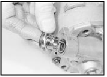
3 Unscrew the two securing bolts, and remove the pump cover (see illustration).
27.3 Removing the oil pump cover
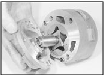
4 Lift the inner and outer rotors from the pump casing.
5 Unscrew the pressure relief valve plug from the pump cover, recover the washer, and withdraw the spring and plunger (see illustrations).
27.5a Unscrew the pressure relief valve plug and washer . . .
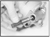
27.5b . . . and withdraw the spring and plunger
Inspection
6 Thoroughly clean all components in petrol or
paraffin, and wipe dry using a non-fluffy rag.
7 Examine the rotors and the pump casing for signs of excessive wear on the machined surfaces. If wear is evident, the complete pump assembly must be renewed, as spare parts are not available individually.
Reassembly
8 Commence reassembly by lubricating the
relief valve plunger. Fit the plunger and the
spring, and screw the plug into place,
ensuring that the washer is in place under the
plug.
9 Lubricate the rotors, and fit them to the pump casing with the punch marks facing the pump cover (see illustration).
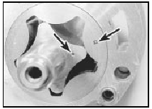
27.9 The punch marks (arrowed) on the oil pump rotors must face the pump
cover
10 Refit the pump cover and tighten the securing bolts.
11 Prime the pump before refitting.
Oil pump drive chain and sprockets - examination and renovation
1 Examine all the teeth on the sprockets. If the teeth are “hooked” in appearance, renew the sprockets.
2 Examine the chain tensioner for wear, and renew it if necessary.
3 Examine the chain for wear. If it has been in operation for a considerable time, or if when held horizontally (rollers vertical) it takes on a deeply-bowed appearance, renew it.
See also:
Camshaft and cam followers - removal, inspection and refitting
Note: A new camshaft oil seal should be used
when refitting the camshaft.
Removal
1 Remove the cylinder head.
2 Hold the camshaft stationary using a
suitable spanner on the cast boss behind the
...
Fluid leak check (Every 6000 miles (10 000 km) or 6 months)
1 Visually inspect the engine joint faces,
gaskets and seals for any signs of water or oil
leaks. Pay particular attention to the areas
around the rocker cover, cylinder head, oil
filter and sump ...
Hydraulic pipes and hoses - renewal
Note: Before starting work, refer to the
warning at the beginning of Section 3
concerning the dangers of hydraulic fluid.
1 Always disconnect a flexible hose by
prising out the spring anchor clip ...
