Carburettors (all types) - dismantling and reassembly
1 A complete strip-down of a carburettor is unlikely to cure a fault which is not immediately obvious without introducing new problems. If persistent carburation problems are encountered, it is recommended that the advice of a Ford dealer or carburettor specialist is sought.
2 If it is decided to go ahead and service a carburettor, check the cost and availability of spare parts before commencement. Obtain a carburettor repair kit, which will contain the necessary gaskets, diaphragms and other renewable items.
3 When working on carburettors, scrupulous cleanliness must be observed and care must be taken not to introduce any foreign matter into components. Carburettors are delicate instruments and care should be taken not to disturb any components unnecessarily.
4 Referring to the relevent exploded view of the carburettor (see illustrations), remove each component part whilst making a note of its fitted position. Make alignment marks on linkages etc.
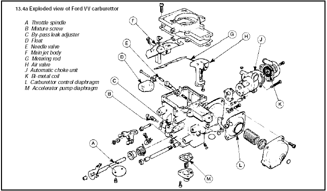
13.4a Exploded view of Ford VV carburettor
A Throttle spindle
B Mixture screw
C By-pass leak adjuster
D Float
E Needle valve
F Main jet body
G Metering rod
H Air valve
J Automatic choke unit
K Bi-metal coil
L Carburettor control diaphragm
M Accelerator pump diaphragm
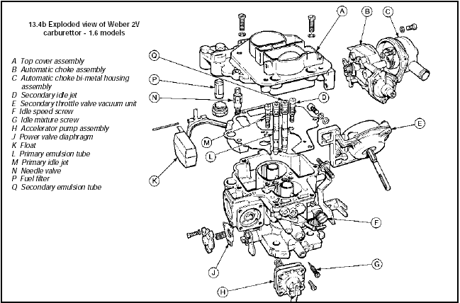
13.4b Exploded view of Weber 2V carburettor - 1.6 models
A Top cover assembly
B Automatic choke assembly
C Automatic choke bi-metal housing assembly
D Secondary idle jet
E Secondary throttle valve vacuum unit
F Idle speed screw
G Idle mixture screw
H Accelerator pump assembly
J Power valve diaphragm
K Float
L Primary emulsion tube
M Primary idle jet
N Needle valve
P Fuel filter
Q Secondary emulsion tube
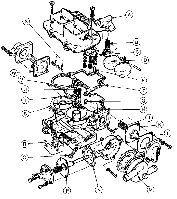
13.4c Exploded view of Weber 2V carburettor - 2.0 litre models up to 1985
A Top cover assembly
B Fuel filter
C Power valve assembly
D Float
E Needle Valve
F Gasket
G Main jet
H Main body assembly
J Primary idle jet assembly
K Accelerator pump diaphragm
L Accelerator pump gasket
M Automatic choke bi-metal housing assembly
N Automatic choke assembly
P Vacuum pull-down diaphragm assembly
Q Idle mixture screw
R Idle speed screw
S Emulsion tube
T Accelerator pump jet
U Air correction jet
V Accelerator pump outlet check ball valve assembly
W Low vacuum enrichment diaphragm
X Secondary idle jet and holder
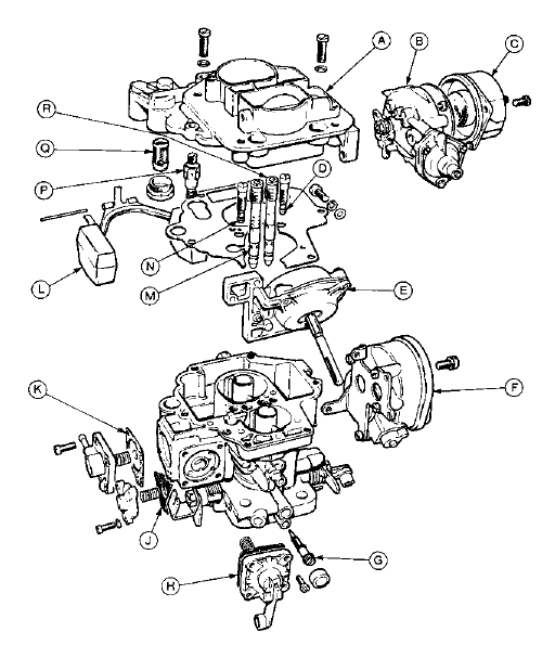
13.4d Exploded view of Weber 2V carburettor - 2.0 litre models from 1985
A Top cover assembly
B Automatic choke assembly
C Automatic choke bi-metal housing
D Secondary idle jet
E Secondary throttle valve vacuum unit
F Stepper motor
G Idle mixture screw
H Accelerator pump assembly
J Power valve diaphragm
K Low vacuum enrichment diaphragm
L Float
M Primary emulsion tube
N Primary idle jet
P Needle valve
Q Fuel filter
R Secondary emulsion tube
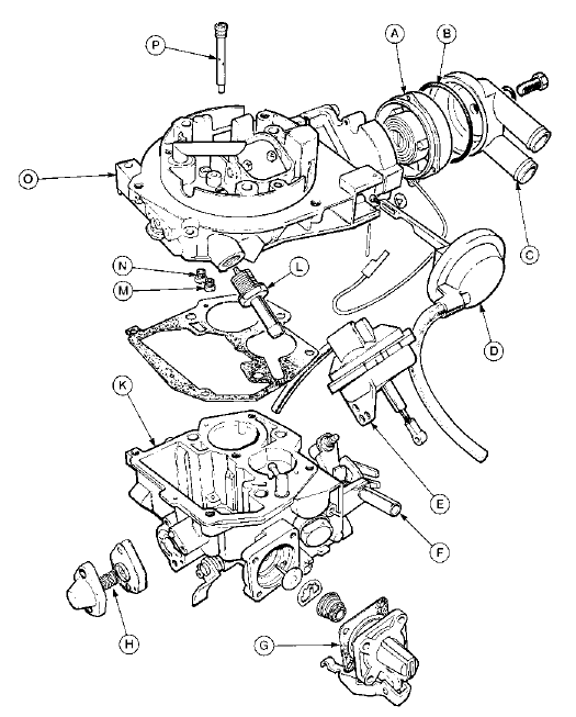
13.4e Exploded view of Pierburg 2V carburettor
A Automatic choke bi-metal housing
B O-ring
C Automatic choke coolant housing
D Automatic choke vacuum pull-down unit
E Secondary throttle valve vacuum unit
F Idle speed screw
G Accelerator pump diaphragm
H Power valve assembly
K Carburettor body
L Fuel inlet pipe and filter
M Primary main jet
N Secondary main jet
O Top cover assembly
P Idle jet
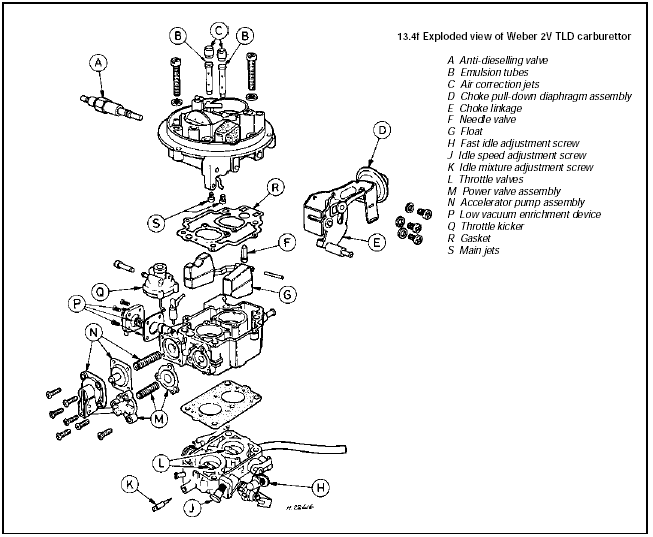
13.4f Exploded view of Weber 2V TLD carburettor
A Anti-dieselling valve
B Emulsion tubes
C Air correction jets
D Choke pull-down diaphragm assembly
E Choke linkage
F Needle valve
G Float
H Fast idle adjustment screw
J Idle speed adjustment screw
K Idle mixture adjustment screw
L Throttle valves
M Power valve assembly
N Accelerator pump assembly
P Low vacuum enrichment device
Q Throttle kicker
R Gasket
S Main jets
5 Reassemble the carburettor in the reverse order to dismantling, using new gaskets, Orings etc. Be careful not to kink any diaphragms.
See also:
Timing belt renewal - CVH engines (Every 36 000 miles or 3
years)
Refer to Chapter 2, Part B. ...
Starting and charging systems
The engine electrical system includes all charging, starting and
ignition system components and the engine oil pressure sensor. ...
Engine/manual gearbox assembly - reconnection and refitting
1.8 litre (R2A type)
1 Reverse the procedure described in Section
10, noting the following points.
2 Before attempting to reconnect the engine
to the gearbox, check that the clutch friction
disc ...
