Distributor (OHC models) - removal and refitting
Note: During production the engine ignition timing is accurately set using a microwave process, and sealant is applied to the distributor clamp bolt. Removal of the distributor should be avoided except where excessive bearing wear has occurred due to high mileage or during major engine overhaul.
A timing light will be required to check the ignition timing after refitting the distributor.
All models except early
“Economy”
Removal
1 Disconnect the battery negative lead.
2 If necessary, identify each HT lead for position, so that the leads can be refitted to their correct cylinders, then disconnect the leads from the spark plugs by pulling on the connectors, not the leads.
3 Where applicable, unclip the screening can from the top of the distributor and disconnect the earth strap. On fuel injection models, disconnect the crankcase ventilation hose from the air inlet hose, then disconnect the air inlet hose from the inlet manifold and the airflow meter for improved access.
4 Prise away the spring clips with a screwdriver, or remove the two securing screws, as applicable, and lift off the distributor cap.
5 Disconnect the HT lead from the coil by pulling on the connector, not the lead, then slide the HT lead holder from the clip on the camshaft cover, and withdraw the distributor cap.
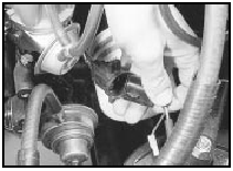
6 Where applicable, disconnect the vacuum pipe from the vacuum advance unit on the side of the distributor (see illustration).
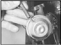
15.6 Disconnecting vacuum pipe from vacuum advance unit - Bosch distributor
7 Using a suitable socket or spanner on the
crankshaft pulley bolt, turn the crankshaft to
bring No 1 cylinder to the firing point. If the
distributor cap is secured by clips, make sure
that the clips stay clear of the distributor
moving parts. No 1 cylinder is at the firing
point when:
a) The relevant timing marks are in
alignment.
b) The tip of the rotor arm is pointing to the position occupied by the No 1 cylinder HT lead terminal in the distributor cap. Note that the position of No 1 HT lead terminal is identified by a pip or a number “1” c) On Lucas distributors, the cut-out in the trigger vane is aligned with the sensor (see illustration)
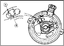
15.7a Lucas distributor showing trigger vane position No 1 cylinder at firing
point
A Trigger vane cut -out B Sensor
d) On Bosch distributors, the tip of the rotor arm is aligned with the scribed line on the distributor body (where applicable, remove rotor arm and dust cover, then refit rotor arm to check alignment with scribed line) (see illustration)
15.7b Rotor arm tip aligned with scribed line on distributor body - Bosch
distributor
e) On Motorcraft distributors, the tip of the rotor arm is aligned with a notch in the distributor body. Mark the relevant notch (there may be several) for reference when refitting. Also, the leading edge of one of the trigger vane segments is aligned with the rib on the sensor (remove the two securing screws and lift off the rotor arm to view the trigger vane and sensor) (see illustration).
15.7c Trigger vane segment leading edge aligned with sensor rib - Motorcraft
distributor
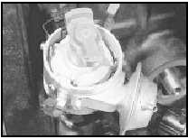
8 Disconnect the distributor wiring plug, where applicable depressing the locking tab(s). Pull on the plug, not the wiring (see illustration).
15.8 Disconnecting distributor wiring plug - Bosch distributor
9 Make alignment marks between the distributor body and the cylinder block.
10 Scrape the sealant from the distributor clamp bolt, then unscrew and remove the bolt and clamp (see illustration).
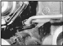
15.10 Unscrewing distributor clamp bolt - Bosch distributor
11 Withdraw the distributor from the cylinder block. As the distributor is removed, the rotor arm will turn clockwise due to the skew gear drive. Note the new position of the rotor arm relative to the distributor body, if necessary making an alignment mark (some distributors already have an alignment mark).
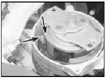
12 Check the distributor spindle for excessive side-to-side movement. If evident, the distributor must be renewed, as the only spares available are the cap, rotor arm, module (where applicable), and driveshaft O-ring (see illustration).
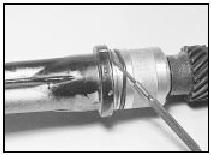
15.12 Removing distributor driveshaft Oring - Motorcraft distributor
Refitting
13 Commence refitting by checking that No 1
cylinder is still at the firing point. The relevant
timing marks should be aligned. If the engine
has been turned whilst the distributor has
been removed, check that No 1 cylinder is on
its firing stroke by removing the No 1 cylinder
spark plug and placing a finger over the plug
hole. Turn the crankshaft until compression
can be felt, which indicates that No 1 piston is
rising on its firing stroke. Continue turning the
crankshaft until the relevant timing marks are
in alignment.
14 Turn the rotor arm to the position noted in paragraph 11. If a new distributor is being fitted, and no alignment marks are present, transfer the marks from the old distributor to the new distributor.
15 Hold the distributor directly over the aperture in the cylinder block with the previously made marks on the distributor body and cylinder block aligned, then lower the distributor into position. Again, if a new distributor is being fitted, transfer the alignment mark from the old distributor body to the new distributor body. As the skew gear drive meshes, the rotor arm will turn anti-clockwise.
16 With the distributor fitted and the marks on the distributor body and cylinder block aligned, check that the rotor arm is positioned as described in paragraph 7 - if not, withdraw the distributor, re-position the driveshaft and try again.
17 Refit the clamp, then insert and tighten the bolt. Do not fully tighten the bolt at this stage.
18 Refit the distributor wiring plug, and where applicable reconnect the vacuum pipe, and refit the dust cover and/or rotor arm.
19 Refit the distributor cap, and reconnect the HT leads to the spark plugs and coil.
Ensure that the leads are refitted to their correct cylinders.
20 Where applicable, refit the screening can to the top of the distributor and reconnect the earth strap. On fuel injection models, reconnect the air inlet hose, ensuring that the clips are correctly aligned (refer to illustration, Section 15, Chapter 4, Part B).
21 Reconnect the battery negative lead.
22 Check and if necessary adjust the ignition timing.
Early “Economy” models
Removal
23 Removal of the distributor fitted to these
models is a similar process to that described
above.
Refitting
24 Turn the crankshaft to bring No 1 cylinder
to the firing point, with the 16º BTDC mark on
the crankshaft pulley aligned with the pointer
on the crankshaft front oil seal housing, as
described above.
25 Fit the new distributor to the engine as described above, then proceed as follows.
26 Cut the original distributor wiring plug from the wiring loom. Make the cut close to the connector.
27 Strip back 10 mm of insulation from each of the wires on the wiring loom, and on the adapter loom supplied with the new distributor.
28 Solder the adapter loom wires to the corresponding identically coloured wires in the main loom.
29 Carefully insulate each individual soldered joint using insulating tape, then apply tape to cover the join between the looms.
30 Fit a new distributor cap (and screening can, where applicable), and connect the HT leads.
31 Connect the adapter loom to the distributor.
32 Start the engine, and adjust the ignition timing to the value given in the Specifications at the beginning of this Chapter. Work as described above whilst noting that the vacuum pipe must be left connected.
See also:
Automatic transmission operation (if equipped)
Brake-shift interlock
This vehicle is equipped with a brake-shift interlock feature that prevents
the gearshift lever from being moved from P (Park) unless the brake pedal is
depressed. If you can ...
Pistons/connecting rods - removal and refitting
Removal
1 Remove the sump, as described in Section
8, and the cylinder head, as described in
Section 7.
2 Check that the connecting rod and cap
have adjacent numbers at their big-end to
indicate ...
Camshaft and cam followers - removal, inspection and refitting
Note: A new camshaft oil seal should be used
when refitting the camshaft.
Removal
1 Remove the cylinder head.
2 Hold the camshaft stationary using a
suitable spanner on the cast boss behind the
...
