Steering wheel - centralising
1 This operation is for correcting small errors in steering wheel centralisation - up to 60º.
For larger errors, remove the steering wheel and make a rough correction by repositioning the wheel on refitting.
2 Drive the vehicle in a straight line on a level surface. Note the angle by which the steering wheel deviates from the desired straight-ahead position.
3 Raise the front of the vehicle by driving it onto ramps, or with a jack and axle stands.
4 Slacken both tie-rod end locknuts. Also slacken the steering rack bellows outer clips.
5 Make alignment marks between each tie-rod end and its rod, so that the amount of rotation applied can be accurately determined see illustration).
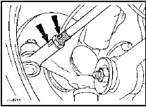
23.5 Make alignment marks (arrowed) between each tie-rod end and its rod when
centralising the steering wheel
6 Turn both tie-rods in the same direction to correct the steering wheel position. As a rough guide, 19º of tie-rod rotation will change the steering wheel position by 1º. To correct a clockwise error at the steering wheel, rotate both tie-rods anti-clockwise (when viewed from the left-hand side of the vehicle), and the reverse to correct an anticlockwise error. Both tie-rods must be rotated by the same amount.
7 Tighten the bellows clips and the tie-rod end locknuts when adjustment is correct.
Lower the vehicle.
See also:
Electronic modules - removal and refitting
Note: Refer to Section 1 for precautions to be
observed when working with electronic
modules.
1 Disconnect the battery negative lead.
All ESC modules except ESC
(early “Economy” models)
2 All mo ...
Handbrake cables - renewal
1 Chock the front wheels, then fully release
the handbrake.
2 Raise and support the vehicle at the rear
with axle stands (see “Jacking and Vehicle
Support”).
Primary cable
3 Extract the spring c ...
Ford Escort maintenance schedule
The maintenance intervals in this manual are provided with the
assumption that you, not the dealer, will be carrying out the work. These
are the minimum maintenance intervals recommended by the
man ...
