Manual steering gear - removal and refitting
Note: A balljoint separator tool will be required for this operation.
Removal
1 Set the front wheels in the straight-ahead
position. Ensure that the steering lock is
engaged and remove the ignition key.
2 Apply the handbrake. Loosen the front roadwheel nuts, jack up the front of the vehicle and support on axle stands.
3 Remove the roadwheels. On P100 models, mark the position of the roadwheels in relation to the wheel studs.
4 Unscrew and remove the clamp bolts securing the intermediate shaft flexible coupling to the steering gear.
5 If the original steering gear is to be refitted, mark the coupling in relation to the pinion. The pinion has a master spline, but making alignment marks will aid refitting.
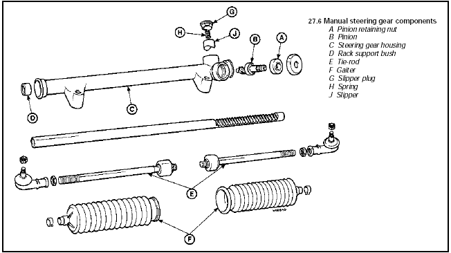
6 Slacken the tie-rod end locknuts (see illustration).

27.6 Manual steering gear components
A Pinion retaining nut
B Pinion
C Steering gear housing
D Rack support bush
E Tie-rod
F Gaiter
G Slipper plug
H Spring
J Slipper
7 Remove the split pins and unscrew the castellated nuts from the tie-rod end-to-hub carrier balljoints.
8 Using a balljoint separator tool, disconnect the tie-rod ends from the hub carriers.
9 Unscrew the two steering gear-to-front suspension crossmember securing bolts, and withdraw the steering gear from under the vehicle.
10 If required, remove the tie-rod ends.
Refitting
11 Refitting is a reversal of removal, bearing
in mind the following points.
12 If new steering gear is being fitted, the central pinion position can be ascertained by halving the number of turns required to move the rack from lock to lock.
13 Where applicable, align the marks made on the coupling and pinion.
14 When tightening the steering gear-to-front suspension crossmember bolts, the following procedure should be used. Tighten the bolts to the specified “clamping” torque, then loosen the bolts fully. Re-tighten to the specified “snug” torque and then further tighten the bolts through the specified angle.
15 Tighten all fixings to the specified torque, and use new split pins on the balljoint castellated nuts.
16 On P100 models, align the previously made marks on the roadwheels and wheel studs.
17 On completion, check the front wheel alignment.
See also:
Major operations requiring engine removal
The following work can only be carried out
after removal of the engine from the car:
a) Crankshaft main bearings - renewal .
b) Crankshaft - removal and refitting.
c) Flywheel - removal and refitt ...
Starting
Positions of the ignition
1. LOCK, locks the steering wheel,
gearshift lever (automatic transaxle
only) and allows key removal. On
vehicles with a manual transaxle
push the key in while turning t ...
Inlet manifold - removal and refitting
Note: A new gasket will be required on
refitting.
Carburettor models
Removal
1 Disconnect the battery negative lead.
2 Remove the air cleaner as described in Part
A of this Chapter.
3 Refer to ...
