Ignition switch and lock barrel - removal and refitting
Removal
1 Disconnect the battery negative lead.
2 For improved access, remove the securing screws and unclip the lower and upper steering column shrouds.
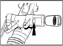
3 Insert the ignition key and turn to position “I”, then, working through the access hole, depress the spring clip using a suitable tool and pull the key to withdraw the lock barrel and cylinder from the ignition switch housing.
The spring clip access hole is shown (see illustration).

4.3 Ignition switch lock barrel spring clip location (arrowed)
Note that, on certain models, the spring clip must be released by inserting the tool through a small circular hole at the top of the switch housing, above the rectangular slot shown. Slight movement of the key may be necessary to allow removal of the barrel and cylinder.
4 To remove the lock barrel from the cylinder insert the key fully into the barrel and remove the retaining circlip, taking care not to damage the circlip location, then withdraw the key approximately 5.0 mm (0.2 in) to retract the lock barrel securing lug, and withdraw the barrel from the cylinder.
5 To remove the ignition switch, disconnect the wiring plug, then remove the two grub screws and withdraw the switch.
Refitting
6 Refitting is a reversal of removal, bearing in
mind the following points.
7 Note that the lock barrel can only be fitted to the cylinder in one position, and check with the key fully inserted that the barrel can be turned from position “O” to “Ill” satisfactorily.
8 The open jaws of the lock barrel retaining circlip must align with the keyway register on the cylinder, and the cylinder retaining circlip must locate in the slot in the ignition switch housing.
9 On completion, check the operation of the steering lock and ignition switch in all positions.
Direction indicator and hazard warning flasher switch assembly - renewal
1 Disconnect the battery negative lead.
2 Remove the securing screws and unclip the lower and upper steering column shrouds.
3 Remove the two securing screws and disconnect the two wiring plugs, then withdraw the switch from the steering column.
4 Refitting is a reversal of removal.
Direction indicator/hazard warning flasher relay - renewal
1 Disconnect the battery negative lead.
2 The relay is located on a bracket above the steering column. Access is gained either by removing the driver’s side lower facia panel or the instrument panel.
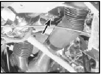
3 Unclip the relay from the bracket, and disconnect the wiring plug (see illustration).

6.3 Direction indicator/hazard warning flasher relay location (arrowed)
4 Refitting is a reversal of removal. Check for correct operation before refitting the facia panel or instrument panel.
Lighting and wash/wipe switch assembly - renewal
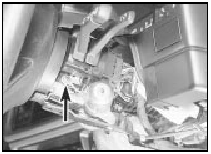
The procedure is identical to that described for the direction indicator switch, except for the additional removal and refitting of an earth lead (see illustration).

7.1 Lighting and wash/wipe switch assembly earth lead securing screw
(arrowed)
Reversing lamp switch - renewal
1 For automatic transmission models, refer to Chapter 7, Part B. For manual gearbox models, proceed as follows: 2 Disconnect the battery negative lead.
3 Apply the handbrake, jack up the front of the vehicle and support on axle stands (see “Jacking and Vehicle Support”).
4 Working underneath the vehicle, disconnect the wiring plug, then unscrew the switch from the gearbox extension housing.
5 Refitting is a reversal of removal, but make sure that the wiring is routed clear of the exhaust system.
See also:
Rear parcel shelf - removal and refitting
Removal
1 Open the tailgate fully and disengage the
parcel shelf lifting strap loops from the tailgate
retaining knobs.
2 Lift out the parcel shelf pivot pins from their
notches in the support br ...
Auxiliary shaft - removal, inspection and refitting
Note: A new gasket should be used when
refitting the auxiliary shaft cover (see text).
Removal
1 Remove the timing belt and the auxiliary
shaft sprocket.
2 Remove the distributor.
3 Remove the m ...
Specifications
General
Engine type . . . . . . . . . . . . . . . . . . . . . . . . . . . . . . . . . .
. . . . . . . . . . . . . Four-cylinder, in-line overhead valve
Capacity:
1.1 litre:
OHV engines . . . . . ...
