Front direction indicator lamp unit - removal and refitting
1 Disconnect the battery negative lead.
Models up to 1987
Low specification
2 Push the lamp unit rearwards into the
bumper until the plastic retaining tang is heard
to click in the locked position.
3 Withdraw the lamp unit from the front of the bumper and disconnect the wiring plug (see illustration).
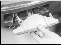
44.3 Withdrawing a front direction indicator lamp unit - “low specification”
models up to 1987
4 Commence refitting by reconnecting the wiring plug.
5 Release the retaining tang, then refit the lamp unit to the bumper, ensuring that the pivot on the lamp unit engages with the slot in the bumper. Reconnect the battery.
High specification
6 Press the release lever at the top of the
lamp unit upwards, and withdraw the unit
from the bumper. Disconnect the wiring plug.
7 To refit, reconnect the wiring plug, then push the lamp unit into the bumper until it locates securely. Reconnect the battery.
All models from 1987
8 Working in the engine compartment,
unhook the lamp unit anchor spring from its
anchorage next to the headlamp, then
withdraw the lamp unit sideways from its
recess (see illustrations). Disconnect the
bulbholder by twisting it anti-clockwise.
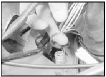
44.8a Unhook the front direction indicator lamp unit anchor spring . . .
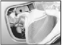
44.8b . . . and withdraw the lamp unit
9 Refitting is a reversal of removal, but ensure that the locating pins on the lamp unit engage with the corresponding holes in the headlamp mounting panel.
See also:
Engine mountings - renewal
1 The engine mountings incorporate
hydraulic dampers and must be renewed if
excessive engine movement is evident.
2 Working in the engine compartment,
unscrew the central nuts securing the engine
...
Steering wheel - removal and refitting
Removal
1 According to model, either pull off the
steering wheel trim, prise out the insert which
carries the Ford motif at the centre, or carefully
prise up and lift off the horn push followed by ...
Boot lid (Saloon models) - removal and refitting
Removal
1 Open the boot lid, and place protective
covers (old rags or cardboard) beneath the
corners of the lid, and over the rear wings to
prevent damage to the paintwork.
2 Where applicable, di ...
