Load apportioning valve (anti-lock braking system) - removal and refitting
Note: Before starting work, refer to the warning at the beginning of Section 3 concerning the dangers of hydraulic fluid.
Removal
1 Raise the car on a hoist or drive the rear of
the car up on ramps. The rear wheels must
not hang free.
2 If removing the right-hand side load apportioning valve on fuel-injected models, undo the nut and bolt securing the fuel pump mounting bracket to the underbody. Move the fuel pump aside to gain access to the valve.
3 Disconnect the hydraulic pipes at the valve then plug the pipes and orifices to prevent loss of fluid and dirt ingress.
4 As an aid to reassembly, accurately mark the position of the valve adjusting bracket on the rear suspension arm. This will ensure that the valve adjustment is not lost when refitting.
5 Undo the nuts and remove the stud plate securing the adjusting bracket to the suspension arm (see illustration).
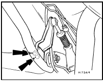
22.5 Load apportioning valve adjusting bracket retaining nut locations
(arrowed)
6 Undo both rear suspension arm inner mounting nuts and remove the load apportioning valve mounting plate.
7 Undo the bolts securing the valve to the mounting plate and remove the valve and adjusting bracket from under the car (see illustration).
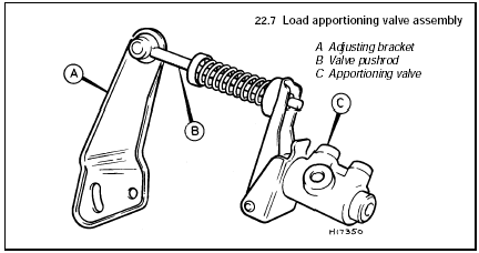
22.7 Load apportioning valve assembly
A Adjusting bracket
B Valve pushrod
C Apportioning valve
8 If required separate the valve pushrod from the adjusting bracket by levering off the pushrod trunnion with a screwdriver (see illustration). Lubricate the trunnion rubber bush to aid removal.
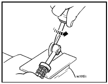
22.8 Separating apportioning valve pushrod from adjusting bracket
Refitting 9 If a new valve is being fitted it will be supplied with nylon setting spacers and ties attached, to ensure correct adjustment of the valve. Leave these in position until the valve is installed.
10 Refit the pushrod trunnion to the adjusting bracket using a suitable socket and a vice.
11 Locate the valve on its mounting plate and secure with the retaining bolts.
12 Position the mounting plate over the suspension arm mounting bolts and secure with the nuts tightened to the specified torque.
13 Reconnect the hydraulic pipes to the valve.
14 Refit the stud plate and adjusting bracket to the suspension arm ensuring that the previously made marks are aligned if the original components are being refitted. Secure the adjusting bracket with the retaining nuts tightened to the specified torque.
15 If a new valve assembly is being fitted, remove the nylon setting spacers and ties.
16 Where applicable refit the fuel pump mounting bracket.
17 Lower the car to the ground.
18 Bleed the hydraulic system as described in Section 23.
19 It is recommended that the load apportioning valve adjustment be checked by a dealer if the original unit has been refitted.
Special gauges are needed for this operation and it is not a DIY proposition.
See also:
Intercooler - removal and refitting
1985 models
Removal
1 Disconnect the battery negative lead.
2 Remove the air cleaner as described in
Section 2.
3 Remove the intercooler upper and lower air
hoses (see illustration).
22.3 Int ...
Front tie-bar - removal and refitting
Pre-May 1983 1.1 litre models
Removal
1 Jack up the front of the car and support it
on stands (see “Jacking and Vehicle Support”).
2 Unscrew and remove the nut which holds
the tie-bar to the larg ...
Specifications
System type . . . . . . . . . . . . . . . . . . . . . . . . . .
. . . . . . . . . . . . . . . . . Diagonally split dual circuit, hydraulic with
pressure regulating
valve to rear brakes. Servo ass ...
