Steering column - removal, overhaul and refitting
Removal
1 Disconnect the battery negative terminal.
2 Turn the ignition key and rotate the steering wheel to bring the front roadwheels to the straight-ahead position.
3 Working within the engine compartment, unscrew and remove the pinch-bolt which holds the steering shaft to the splined pinion shaft of the rack-and-pinion steering gear.
4 Remove the steering wheel, as described in Section 22.
5 Remove the direction indicator cam from the top end of the steering shaft (where fitted).
6 Extract the fixing screws and remove the upper and lower shrouds from the upper end of the steering column (see illustrations).
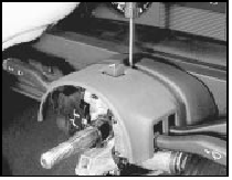
25.6a Removing the steering column upper . . .
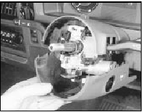
25.6b . . . and lower shrouds on a pre-1986 model . . .
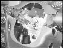
25.6c . . . and on a post-1986 version
7 Remove the insulation panel from the lower part of the facia (see illustration).
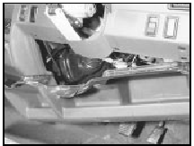
25.7 Removing the facia lower panel
8 Extract the screw, remove the bonnet release lever mounting and place it to one side (see illustration).
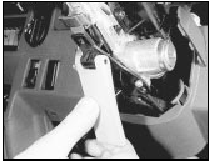
25.8 Removing the bonnet release lever
9 Take out the fixing screws and remove the switches from the steering column (see illustrations).
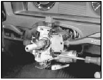
25.9a Steering column switch removal on a pre-1986 model . . .
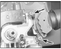
25.9b . . . and switch retaining screw locations (arrowed) on post-1986
versions
10 Disconnect the wiring harness multi-plug at the side of the column.
11 Unbolt the upper and lower clamps from the steering column and then withdraw the column/shaft into the vehicle. If any difficulty is experienced in separating the lower shaft from the pinion gear, prise the coupling open very slightly with a screwdriver. Note that on certain models (including all Cabriolets), an additional bracing bracket may be fitted between the column support bracket and the body (see illustrations).
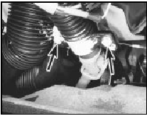
25.11a Steering column lower mounting clamp bolts (arrowed)
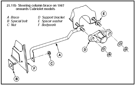
25.11b Steering column brace on 1987 onwards Cabriolet models
A Brace
B Special bolt
C Nut
D Support bracket
E Spacer washer
F Bodywork
Overhaul 12 Wear in the column bearings can be rectified by renewing them. Access to them is obtained by extracting the tolerance ring from the upper end of the column and then withdrawing the shaft from the lower end of the column. The lower bearing and spring will come with it. Make sure that the steering column lock is unlocked before withdrawing the shaft.
13 If the upper bearing is to be renewed, first remove the lock assembly by drilling out the shear-head bolt. The upper bearing may now be levered out of its seat.
14 Commence reassembly by tapping the new upper bearing into its seat in the lock housing. Refit the column upper clamp and bush.
15 Locate the column lock on the column tube and screw in a new shear-head bolt until its head breaks off.
16 Insert the conical spring into the column tube so that the larger diameter end of the spring is against the lowest convolution of the collapsible section of the column tube.
17 Slide the lower bearing onto the shaft so that its chamfered edge will mate with the corresponding one in the column lower bearing seat when the shaft is installed.
18 Insert the shaft into the lower end of the steering column. Make sure that the lock is unbolted and pass the shaft up carefully through the upper bearing.
19 Fit the bearing tolerance ring and waved washer.
Refitting
20 Fit the direction indicator cancelling cam
to the top of the shaft, making sure that the
peg will be uppermost when the column is in
the in-car attitude (where fitted).
21 Fit the steering wheel to the shaft, screwing on the nut sufficiently tightly to be able to pull the lower bearing into the column tube with the bearing slots correctly aligned with the pegs on the tube.
22 Refit the column, making sure to engage the coupling at its lower end with the splined pinion shaft.
23 Bolt up the column upper and lower clamps.
24 Reconnect the wiring harness multi-plug.
25 Refit the combination switches to the steering column.
26 Reconnect the bonnet release lever.
27 Fit the column shrouds.
28 Check that the steering wheel is correctly aligned (wheels in the straight-ahead position). If not, remove the steering wheel and realign it (see also Section 23).
29 Tighten the steering wheel nut to the specified torque and then insert the motif or horn push into the centre of the steering wheel.
30 Refit the insulation panel to the lower facia.
31 Tighten the coupling pinch-bolt at the base of the steering shaft.
32 Reconnect the battery negative terminal.
See also:
Vacuum servo (conventional braking system) - removal and refitting
Caution: Refer to the
precautions in Section 1.
Removal
1 To remove the servo, first remove the
master cylinder.
2 Disconnect the vacuum hose from the
servo (see illustration).
14.2 Servo vac ...
Central (single-point) Fuel Injection (CFI) system
The system is best described by dividing it into four separate
sub-systems: air, fuel, engine management (EEC IV system), and ignition. ...
Steering intermediate shaft and flexible coupling - removal and refitting
Removal
1 Apply the handbrake, jack up the front of
the vehicle and support on axle stands.
2 Working in the engine compartment,
unscrew the bolt securing the intermediate
shaft to the inner colu ...
