Spark control system components (carburettor models) - removal and refitting
Spark delay and sustain valves 1 Disconnect the vacuum pipes at the valve and withdraw the valve.
2 When refitting a spark delay valve, the valve must be positioned with the black end (marked “CARB”) towards the carburettor and the coloured end (marked “DIST”) towards the distributor or electronic module (as applicable).
3 When refitting a spark sustain valve, the valve must be positioned with the end marked “VAC” towards the carburettor and the side marked “DIST” towards the distributor or electronic module (as applicable).
Ported vacuum switch
4 Where fitted, the switch(es) may be located
in the inlet manifold and/or in an adapter fitted
in one of the coolant hoses.
5 To remove a switch, partially drain the cooling system. Note that there is no need to remove the cylinder block drain plug.
6 Mark the vacuum pipes for location so that they can be refitted in their correct positions, then disconnect the pipes from the switch.
7 Unscrew the valve from its location.
8 Refitting is a reversal of removal, ensuring that the vacuum pipes are correctly connected. Refill the cooling system.
Fuel trap
9 Disconnect the vacuum pipes at the fuel
trap and withdraw the fuel trap.
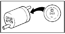
10 When refitting, the fuel trap must be positioned with the black end (marked “CARB”) towards the carburettor, and the white side (marked “DIST”) towards the distributor, electronic module, or ported vacuum switch (as applicable) (see illustration).

22.10 Fuel trap vacuum connection markings
Spark control system additional
components
11 According to model, engine and
equipment, additional components such as
one-way valves or solenoids may also be
fitted as part of the spark control system.
12 The removal and refitting procedures for these components are basically as described previously, and provided that all attachments are marked for position prior to removal, no problems should be encountered.
See also:
Diagram 4b: 1986-on KE-Jetronic fuel injection
Diagram 4b: 1986-on KE-Jetronic fuel injection For starting and charging
circuits see Diagram 1a ...
Brake hydraulic system (conventional braking system) - bleeding
Caution: Refer to the
precautions in Section 1.
General
1 If any of the hydraulic components in the
braking system have been removed or
disconnected, or if the fluid level in the
reservoir has b ...
Maintenance - bodywork, underside and fittings
The general condition of a vehicle’s
bodywork is the one thing that significantly
affects its value. Maintenance is easy but
needs to be regular. Neglect, particularly after
minor damage, can lead ...
