Hydraulic unit (ABS) - removal and refitting
Note: A new gasket must be used between the hydraulic unit and the bulkhead on refitting.
Caution: Refer to the
precautions in Section 1.
Removal
1 Disconnect the battery negative lead.
2 Depressurise the hydraulic system by pumping the brake pedal at least 20 times, or until it becomes hard.
3 Disconnect the six multi-plugs from the hydraulic unit. They are all different, so there is no need to label them. When a plug has a spring clip retainer, lift the clip before pulling out the plug. To release the pump plug, pull back the rubber boot and the plug sleeve (see illustrations).
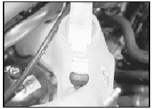
16.3a Disconnecting the low fluid level switch multi-plug . . .
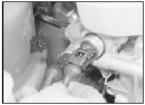
16.3b . . . the main valve multi-plug . . .
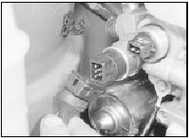
16.3c . . . and the pressure switch multi-plug - ABS
4 Unbolt the earth strap from the unit.
5 Prepare a suitable container to catch spilt fluid. Mark the hydraulic pipes so that they can be refitted in their original positions, then disconnect them from the base of the unit.
Plug the open ends of the pipes and hydraulic unit to prevent fluid leakage and dirt ingress. If fluid is accidentally spilt on the paintwork, wash off immediately with cold water.
6 Working inside the vehicle, remove the lower facia panel from the driver’s side.
7 Remove the clip from the hydraulic unit pushrod on the brake pedal.
8 With an assistant supporting the hydraulic unit, unscrew the four nuts which secure the unit to the bulkhead (see illustration).
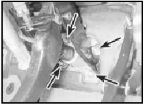
16.8 Hydraulic unit-to-bulkhead securing nuts (arrowed) - ABS
Withdraw the unit from under the bonnet.
9 Recover the gasket fitted between the unit and the bulkhead.
10 Drain the fluid from the reservoir. Do not actuate the pushrod with the unit removed.
11 Dismantling of the hydraulic unit should be limited to the operations described in the following Sections (see illustration).
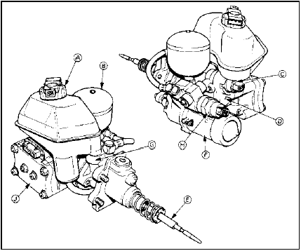
16.11 Hydraulic unit components - ABS
A Fluid reservoir
B Accumulator
C Main valve
D Master cylinder
E Pushrod
F Pump and motor
G Booster
H Pressure switch
J Valve block
Refitting
12 Refitting is a reversal of removal, bearing
in mind the following points.
13 Do not refill the fluid reservoir until reassembly and refitting is complete.
14 Use a new gasket between the hydraulic unit and the bulkhead.
15 Ensure that the hydraulic pipes are reconnected to the correct unions.
16 On completion, bleed the complete hydraulic system and check for leaks around all disturbed components.
See also:
Door handle and lock components - removal and refitting
Door exterior handle
Removal
1 Remove the door trim panel (Section 11).
2 Peel back the waterproof sheet as
necessary to gain access (see illustration).
13.2 Peel back the waterproof sheet for ...
Door lock - removal and refitting
Models up to 1990
1 Remove the door inner trim panel.
2 Where necessary for improved access, peel
back the waterproof plastic sheet from the
door.
3 Withdraw the window channel extension
through ...
Auxiliary warning system components - removal and refitting
General
1 This system monitors the fluid levels and
front brake pads for excessive wear. In the
event of a fluid level dropping below the
specified level, or the brake pads wearing
down to the mi ...
