Instrument panel - removal and refitting
Models up to 1992
1 Disconnect the battery negative lead.
2 Remove the securing screws and unclip the lower and upper steering column shrouds.
3 Where applicable, remove the instrument panel illumination and intermittent wiper rheostats.
4 Unclip the cover for access to the lower right-hand instrument panel surround securing screw (see illustrations).
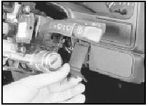
20.4a Unclip the cover . . .
20.4b . . . for access to the lower righthand instrument panel surround
securing screw
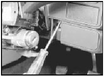
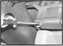
5 Remove the two upper and two lower securing screws, and withdraw the instrument panel surround (see illustration).
20.5 Removing an upper instrument panel surround securing screw
6 On models fitted with a trip computer, unscrew the knurled nut and disconnect the speedometer cable from the speed sender unit on the engine compartment bulkhead.
7 Detach the speedometer cable grommet from the engine compartment bulkhead.
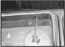
8 Remove the two upper and two lower securing screws, and withdraw the instrument panel sufficiently to disconnect the speedometer cable and the wiring plugs. The speedometer cable can be released by pushing the ribbed surface towards the centre of the cable to free the catch. Remove the instrument panel (see illustration).
20.8 Withdraw the instrument panel and disconnect the wiring plugs
9 Refitting is a reversal of removal but where applicable, ensure that the speedometer cable rubber sleeve is in place over the square Inner drive on the cable connector, and not in the speedometer head.
10 On completion, pull the speedometer cable from within the engine compartment to ensure that the cable is straight between the instrument panel and the bulkhead grommet.
Models from 1992
11 The procedure is as described above but
note that both instrument panel surround
lower securing screws are located beneath
plastic covers (see illustration).
20.11 Removing an instrument panel surround lower securing screw (cover
removed)
12 The steering column shrouds are secured by six screws - five through the lower shroud, and one through the upper shroud.
See also:
Deceleratio sensitive valve (all models with conventional braking system) - removal and refitting
Caution: Refer to the precautions in Section 1.
Removal
1 The deceleration sensitive valve is located on the left-hand side of the engine compartment (see illustrations).
23.1a Early type decele ...
Rear suspension front mounting (Saloon, Hatchback and Estate models) -
renewal
1 Chock the front wheels, jack up the rear of
the vehicle and support on axle stands placed
under the side members.
2 Unscrew and remove the three bolts
securing the relevant front guide plate to ...
Auxiliary air device - removal and refitting
K-Jetronic system
Removal
1 Disconnect the battery earth lead.
2 Disconnect the wiring multi-plug and the
two air hoses from the device which is located
beneath the cold start valve (see illustra ...
