Idle speed and mixture adjustment (Every 6000 miles or 6 months)
Caution: Certain adjustment points in the fuel system are protected by “tamperproof” caps, plugs or seals. In some EEC countries (though not yet in the UK) it is an offence to drive a vehicle with broken or missing tamperproof seals.
Before disturbing a tamperproof seal, satisfy yourself that you will not be breaking any local or national laws by doing so, and fit a new seal after adjustment is complete where required by law. Do not break tamperproof seals on a vehicle which is still under warranty.
Note: Before carrying out any carburettor adjustment, ensure that the contact breaker points, ignition timing and spark plug gaps (as applicable) are set as specified and that the distributor is operating correctly (where applicable). To carry out the adjustments an accurate tachometer will be required and the use of an exhaust gas analyser (CO meter) is also preferable.
Models with Ford VV carburettor
Idle speed
1 With the engine at normal operating
temperature, connect a tachometer in
accordance with the manufacturer’s
instructions.
2 Disconnect the wiring multi-plug from the radiator cooling fan thermostatic switch in the thermostat housing and bridge the two contacts in the plug using a suitable length of wire. This is necessary so that the cooling fan runs continuously during adjustment.
3 On automatic transmission models slacken the adjuster screw on the throttle valve shaft lever to give clearance of 2 to 3 mm (0.079 to 0.118 in) - see Chapter 7, Part B.
4 Ensure that the air cleaner is fitted and that its vacuum hoses are not in any way trapped or pinched, particularly between the air cleaner body and the top face of the carburettor.
5 Run the engine at 3000 rpm for 30 seconds, then allow it to idle and note the idle speed. If using an exhaust gas analyser it should be noted that initially the CO% reading will rise, but then fall and stabilise after a period of 5 to 25 seconds. The CO reading should then be as specified.
Idle mixture
6 If necessary, adjust the idle speed
adjustment screw to give the specified idle
speed (see illustration).
10.6 Idle speed adjustment screw (A) and mixture adjustment screw (B) - Ford
VV carburettor
7 Adjustment of the CO content (mixture) is not normally required during routine maintenance, but if the reading noted in paragraph 5 is not as given in the Specifications first remove the tamperproof plug, prising it free using a small screwdriver.
8 Run the engine at 3000 rpm for 30 seconds, then allow it to idle. Adjust the mixture screw (see illustration 10.6) within 30 seconds. If more time is required run the engine at 3000 rpm again for 30 seconds.
9 Adjust the idle speed if necessary and recheck the CO content.
10 Fit a new tamperproof plug to the mixture adjuster screw on completion. It should be noted that mixture adjustment without a CO analyser is not accurate and therefore not recommended.
11 On completion disconnect the instruments, remove the cooling fan bridging wire and reconnect the multi-plug.
12 On automatic transmission models adjust the downshift linkage (Chapter 7, Part B).
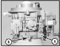
Models with Weber 2V carburettor 13 The procedure is the same as for the Ford VV carburettor as described previously in this Section, but the adjusting screw locations are as shown (see illustrations).
10.13a Weber 2V carburettor idle speed adjustment screw (A) and mixture screw
(B) - XR3 and 1.4 litre models
10.13b Weber 2V carburettor mixture adjustment screw (A) and idle speed
adjustment screw (B) - 1.6 litre models
10.13c Idle speed screw (A) and mixture adjustment screw (B) on Weber 2V TLDM
carburettor (1.1 and 1.3 HCS engines)
Models with Bosch K-Jetronic
fuel injection system
14 The idle speed and fuel mixture
adjustments will normally only be required
after the installation of new components.
Refer to the caution at the beginning of this Section before proceeding.
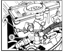
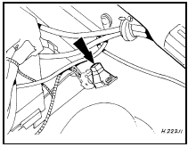
15 On early models the idle speed adjustment screw is located on the rear of the throttle housing, but access is severely limited unless the heater plenum chamber top cover is removed as described in Chapter 4, Part B (see illustration).
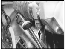
10.15 Idle speed adjustment screw (arrowed) on early K-Jetronic systems
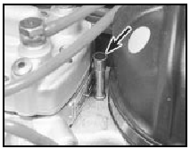
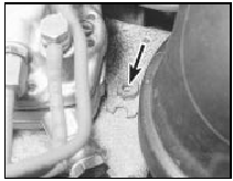
16 On later models the idle speed adjustment screw is located on top of the throttle housing beneath a tamperproof plug (see illustration).
Hook out the plug with a sharp pointed tool to gain access.
10.16 K-Jetronic system idle speed adjustment screw (arrowed) on later models
17 Before making any adjustments, warm the engine up to normal operating temperature and connect a tachometer in accordance with the manufacturer’s instructions.
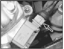
18 Increase the engine speed to 3000 rpm and hold it at this speed for 30 seconds, then allow the engine to idle, check the tachometer reading and if necessary turn the idle speed adjustment screw as required until the engine is idling at the specified speed.
19 To check the mixture adjustment an exhaust gas analyser is needed and should be connected in accordance with the manufacturer’s instructions. A 3 mm Allen key will also be required to make any adjustments.
20 Before making any adjustments to the mixture, ensure that the idle speed is correct.
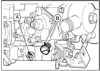
21 Remove the tamperproof plug from the top of the mixture adjustment screw tube on top of the fuel distributor (see illustration).
10.21 K-Jetronic system mixture adjustment screw location (arrowed)
22 Stabilise the exhaust gases (paragraph 18).
23 Insert the Allen key into the mixture screw tube and engage the adjusting screw. Turn the screw as necessary until the correct CO reading is obtained, then if required readjust the idling speed.
24 If the mixture adjustment cannot be finalised within 30 seconds from the moment of stabilising the exhaust gases, repeat the operations in paragraph 18 before continuing the adjustment procedure.
25 On completion fit a new tamperproof plug and disconnect the tachometer and exhaust gas analyser.
Models with Bosch KE-Jetronic
fuel injection system
26 The idle speed and fuel mixture
adjustments will normally only be required
after the installation of new components.
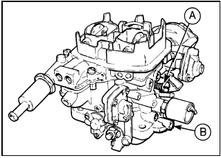
27 The idle speed adjustment screw is located on the side of the throttle housing (see illustration).
10.27 Idle speed adjustment screw (arrowed) on KE-Jetronic system
28 Before making any adjustments, warm the engine up to normal operating temperature and connect a tachometer in accordance with the manufacturer’s instructions.
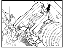
29 Disconnect the wiring multi-plug at the pressure actuator on the side of the fuel distributor (see illustration).
10.29 Pressure actuator wiring multi-plug (arrowed) - KE-Jetronic system
30 Increase the engine speed to 3000 rpm and hold it at this speed for 30 seconds, then allow the engine to idle. Check the tachometer reading and if necessary turn the idle speed adjustment screw as required until the engine is idling at the specified speed.
31 To check the mixture adjustment an exhaust gas analyser is needed and should be connected in accordance with the manufacturer’s instructions. A 3 mm Allen key will also be required to make any adjustments.
32 Before proceeding ensure that the idle speed is correct.
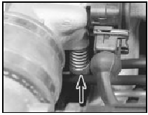
33 Unscrew the tamperproof plug from the mixture adjustment orifice on top of the fuel distributor (see illustration).
10.33 KE-Jetronic system mixture adjustment tamperproof plug (arrowed)
34 Stabilise the exhaust gases (paragraph 30).
35 Insert the Allen key into the mixture adjustment orifice and push down to engage the adjustment screw. Turn the adjustment screw clockwise to increase the CO reading and anti-clockwise to decrease it. Remove the Allen key, plug the orifice and check the CO reading.
36 If the mixture adjustment cannot be finalised within 30 seconds from the moment of stabilising the exhaust gases, repeat the operations in paragraph 30 before continuing the adjustment procedure. Make sure that the Allen key is removed before increasing the engine speed otherwise the fuel distributor will be damaged.
37 Continue adjustment until the correct CO reading is obtained, then if necessary readjust the idle speed.
38 Refit the tamperproof screw and reconnect the pressure actuator multi-plug.
Disconnect the tachometer and exhaust gas analyser.Models with Central (single-point) Fuel Injection (CFI) system 39 Both the idle speed and mixture are controlled by the engine management system.
Adjustment requires the use of specialist equipment. If the idle speed is suspected of being incorrect, the vehicle must be taken to Ford dealer for diagnostic checks and, necessary, adjustment.
Models with Electronic Fuel
Injection (EFI) system
40 Idle speed is controlled by the EEC IV
module, and cannot be adjusted.
41 To adjust the mixture (CO content), first run the engine until it reaches normal operating temperature.
42 Connect a CO meter and a tachometer in accordance with the manufacturer’s instructions.
43 Clear any excess fuel in the inlet manifold by running the engine at 3000 rpm for approximately 15 seconds, then allow the engine to idle.
44 Wait for the test instrument readings to stabilise, then record the CO content and the idle speed.
45 If adjustment of the CO content is required, remove the tamperproof cap from the CO adjustment potentiometer (located on the wing panel behind the left-hand suspension turret) and adjust the screw to obtain the correct CO setting at the specified idle speed (see illustration). Note that any adjustment must be made within 30 seconds of the instrument readings stabilising, otherwise the procedure described in paragraph 43 must be repeated.
10.45 CO adjustment potentiometer location (arrowed) - 1.6 EFI engine
46 On completion of adjustment, stop the engine and disconnect all test equipment. Fit a new tamperproof cap to the CO adjustment potentiometer.
See also:
Ford Escort maintenance schedule
The maintenance intervals in this manual are provided with the
assumption that you, not the dealer, will be carrying out the work. These
are the minimum maintenance intervals recommended by the
man ...
Loudspeakers - removal and refitting
1 Disconnect the battery earth lead.
Facia panel-mounted speakers
Upper
2 Prise the speaker grille from its four
retaining clips in the facia using a thin-bladed
screwdriver.
3 Remove the four s ...
Front and rear brake pad/shoe check (Every 6000 miles (10 000 km) or 6
months)
1 Firmly apply the handbrake, then jack up
the front and rear of the car and support it
securely on axle stands (see “Jacking and
vehicle support”).
2 For a quick check, the front brake disc pads
...
