Fuel pump - testing, removal and refitting
Note: Refer to the warning at the end of Section 1 before proceeding.
Testing
1 The fuel pump may be quite simply tested
by disconnecting the fuel inlet pipe from the
carburettor and placing its open end in a
container.
2 Disconnect the LT lead from the negative terminal of the ignition coil to prevent the engine firing.
3 Actuate the starter motor. Regular welldefined spurts of fuel should be seen being ejected from the open end of the fuel inlet pipe.
4 Where this is not evident and yet there is fuel in the tank, the pump is in need of renewal. The pump is a sealed unit and cannot be dismantled or repaired.
Removal
5 On OHV and HCS engines, the fuel pump is
mounted on the cylinder block and is actuated
by a lever which is in direct contact with an
eccentric cam on the camshaft.
6 On CVH engines, the fuel pump is mounted on the cylinder head and is actuated by a pushrod from an eccentric cam on the camshaft.
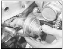
7 To remove the pump, disconnect and plug the fuel inlet and outlet hoses (and on HCS engines, the fuel return hose) at the pump and then unbolt it from the engine (see illustration). Note the fuel hose connections to ensure correct reconnection on refitting.

5.7 CVH engine fuel pump removal
8 Retain any insulating spacers and remove and discard the flange gaskets.
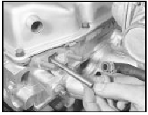
9 On CVH engines, withdraw the push-rod (see illustration).

5.9 Removing the fuel pump push-rod
Refitting 10 Refitting is a reversal of removal, but use new flange gaskets. If crimped type hose clips were used originally, these will have been destroyed when disconnecting the fuel hoses.
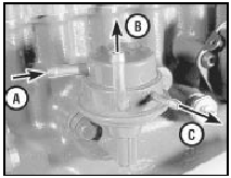
Renew them with conventional nut and screw type clips. Ensure that the fuel hoses are correctly reconnected as noted before removal (see illustration).

5.10 Fuel pump connections on 1.1 and 1.3 litre HCS engines
A Inlet from tank
B Outlet to carburettor
C Return to tank
See also:
Manual gearbox oil level check (Every 12 000 miles (20 000 km) or 12 months)
1 Place the vehicle over a pit, or raise and
support it at front and rear. The vehicle must
be level for an accurate check.
2 If the gearbox is hot after a run, allow it to
cool for a few minutes. ...
Distributor cap and rotor arm (OHC models) - removal and refitting
SOHC models
1 Disconnect the battery negative lead.
2 Where applicable, unclip the screening can
from the top of the distributor and disconnect
the earth strap (see illustration).
13.2 Unclippi ...
Radiator - removal, inspection and refitting
All models except RS Turbo
Pre-1986 models
Removal
1 Drain the cooling system as described in
Chapter 1.
2 Disconnect the battery negative terminal.
3 Release the retaining clips and disconnect
...
