Crankcase emission control system components - removal and refitting
Carburettor and Central Fuel
Injection (CFI) engines
1 On OHV and HCS engines renewal of the
vented oil filler cap and crankcase ventilation
hoses is simply a matter of removing them
from their locations and fitting new parts as
required.
2 On CVH engines the crankcase ventilation filter (where fitted) can be renewed by pulling it out of the air cleaner after disconnecting the hoses (see illustration). Ensure that the sealing grommet is in position in the air cleaner before pushing a new filter into place.
Mechanical (Bosch K- and KEJetronic) fuel injection engines
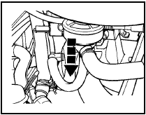
6.2 Crankcase ventilation filter renewal on CVH engines with carburettor -
pull valve in direction of arrow
3 On fuel-injection engines the crankcase ventilation filter is located on the right-hand side of the engine and can be removed after disconnecting the hoses (see illustration). On early versions detach the filter from its support bracket also. Refitting is a reversal of removal.
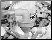
6.3 Crankcase ventilation filter location (arrowed) on KE-Jetronic
fuel-injected engines
4 During the course of production modifications have been made to the crankcase ventilation system on K-Jetronic fuel-injected engines to eliminate stalling and rough idling caused by oil from the crankcase venting system contaminating the throttle housing.
5 Three versions of the system may be encountered. If the stalling and rough idling problems are encountered on cars equipped with the Mk 1 or Mk 2 system, then they should be uprated to Mk 3 specification as described in the following paragraphs. It should be noted that even the latest (Mk 3) level system failed to cure the problem completely and at the beginning of 1986 a revised throttle housing was introduced.
These can be identified by having their idle speed adjustment screw located on the top of the housing under a tamperproof cap, rather than underneath the housing as on early versions. The latest version of throttle housing can be fitted to early cars but the work should be carried out by a dealer, as numerous modifications are involved. The latest version of crankcase ventilation system should always be fitted first however, as follows.
6 As a preliminary operation, remove the idle speed adjustment screw and blow out the idle passage in the throttle housing using air pressure.
7 Refit the screw.
Cars with earliest type (Mk 1) crankcase ventilation system 8 Remove and discard the crankcase ventilation filter vacuum hose.
9 Remove and discard the T-connector and also the short hose (see illustration).
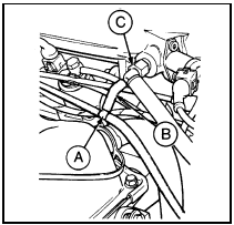
6.9 Components of Mk 1 crankcase ventilation system - fuel-injection models
A T-connector
B Short hose
C Plenum chamber
connector
10 Fit the overrun fuel shut off valve hose to the plenum chamber connector (see illustration).
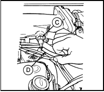
6.10 Fuel shut-off valve hose (D) and plenum chamber connector (C) on Mk 1
type crankcase ventilation system - fuel-injection models
11 Remove and discard the crankcase ventilation filter bracket.
12 Remove and discard the hose which runs between the ventilation filter and the rocker cover.
13 Turn the filter and its hose, which is connected to the air cleaner, so that the small spigot on the filter is uppermost.
14 Fit a new hose between the filter and rocker cover, secure it with the hose clips.
15 Remove and discard the plug from the plenum chamber and in its place screw in the angled connectors. Set the connector as shown (see illustrations).
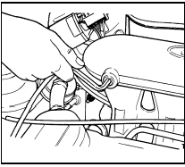
6.15a Unscrewing the plenum chamber plug - fuel-injection models
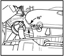
6.15b Correct setting of plenum chamber angled connector - fuel-injection
models
16 Connect the ventilation filter to the angled connector using a new hose.
17 Seat the idle speed screw gently and then unscrew it two complete turns.
18 Bring the engine to normal working temperature and adjust the idle speed and mixture as described in Chapter 1.
Cars with Mk 2 crankcase ventilation
system
19 Remove and discard the crankcase
ventilation filter vacuum hose and fit a
blanking cap to the hose connector on the
throttle housing end of the plenum chamber
(see illustration).
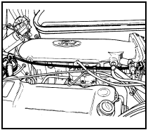
6.19 Mk 2 crankcase ventilation system - fuel-injection models
20 Remove and discard the plug from the plenum chamber and substitute the new angled connector as described in paragraph 15.
21 Fit the new hose between the ventilation filter and the angled connector.
22 Repeat the operations described in paragraphs 17 and 18.
23 Later model cars have the crankcase ventilation filter hose connections as shown (see illustration).
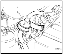
6.23 Mk 3 crankcase ventilation system - fuel-injection models
Electronic Fuel Injection (EFI)
engines
24 A crankcase ventilation filter is fitted in the
hose run to the air cleaner. During the course
of production, modifications have been made
to the crankcase ventilation system, and two
versions of the system may be encountered
(see illustrations).
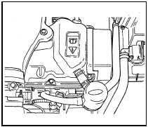
6.24a Early type crankcase ventilation system - 1.6 EFI engine
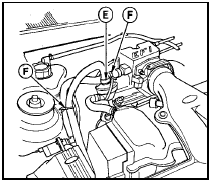
6.24b Later type crankcase ventilation system - 1.6 EFI engine
E Hose clip F Cable-ties
25 Removal and refitting of the filter is simply a matter of disconnecting the relevant hoses.
See also:
Fuel distributor - removal and refitting
Note: Refer to the precautions at the end of
Section 1 before proceeding. It is important to
note that each injection supply pipe connection
in the distributor head has a screw adjacent to
it. The ...
Radio/cassette player - removal and refitting
Standard fixing
1 Disconnect the battery negative lead.
2 Pull off the two control knob assemblies.
3 Release the trim panel by unscrewing the
two securing nuts from the control spindles.
Remove ...
Exterior lamps - removal and refitting
Headlamp
Removal
1 On pre-1986 models, remove the radiator
grille as described in Chapter 11.
2 Working in the engine compartment,
disconnect the headlamp wiring multi-plug
and remove the sidela ...
