Steering column lock - removal and refitting
Note: For ignition switch removal see Chapter 5. A new shear-bolt will be required on refitting.
Removal
1 To remove the ignition switch/column lock,
the shear-head bolt must be drilled out.
2 Access for drilling can only be obtained if the steering column is lowered. To do this, remove the shrouds from the upper end of the column by extracting the fixing screws.
Disconnect the battery earth lead.
3 Unscrew the bonnet release lever mounting screw and position the lever to one side.
4 Disconnect the steering column clamps.
The lower one is of bolt and nut type, while the upper one is of stud and nut design.
5 Lower the shaft/column carefully until the steering wheel rests on the seat cushion.
6 Centre-punch the end of the shear-bolt which secures the steering column lock and then drill it out. Remove the ignition switch/column lock (see illustrations).
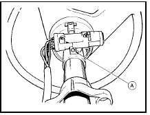
24.6a Steering column lock assembly shear bolt (A) Pre-1986 version shown
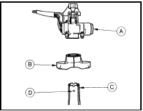
24.6b Steering column lock components - pre-1986 models
A Lock housing
B Upper clamp
C Column tube
D Shear bolt
indentation
Refitting 7 When refitting the lock, check for correct operation and then tighten the new shear-bolt securing bolt until its head breaks off.
8 Raise the steering column and reconnect the clamps.
9 Refit the bonnet release lever and the column shrouds.
10 Reconnect the battery.
See also:
Interior mirror - removal and refitting
Removal
1 The interior mirror is bonded to the
windscreen glass. If it must be removed, grip
the mirror firmly and push it forward to break
the adhesive bond.
2 When refitting the mirror, the fol ...
Auxiliary shaft - removal, inspection and refitting
Note: A new gasket should be used when
refitting the auxiliary shaft cover (see text).
Removal
1 Remove the timing belt and the auxiliary
shaft sprocket.
2 Remove the distributor.
3 Remove the m ...
General information and precautions
General information
The engine electrical system includes all
charging, starting and ignition system
components and the engine oil pressure
sensor. Because of their engine-related
functions, thes ...
