Sump - removal and refitting
Note: New gaskets and sealing strips will be required for refitting, and sealing compound will be required to coat the gasket faces.
Removal
1 If the engine is in the vehicle, proceed as
follows, otherwise proceed to paragraph 12.
2 Disconnect the battery negative lead.
3 Apply the handbrake, jack up the front of the vehicle and support on axle stands (see “Jacking and Vehicle Support”).
4 Drain the engine oil into a container.
5 Remove the starter motor, if necessary.
6 Unscrew the nuts or bolts, as applicable, securing the engine mountings to the crossmember.
7 Working in the engine compartment, unscrew the bolt securing the intermediate shaft to the steering column, swivel the clamp plate to one side, and disconnect the intermediate shaft.
8 Where applicable, detach the brake lines from the crossmember.
9 Support the engine using a hoist, or a bar and blocks of wood resting on the suspension turrets (see illustrations).
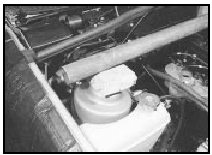
29.9a Make up wooden blocks to fit the front suspension turrets and support a
metal bar . . .
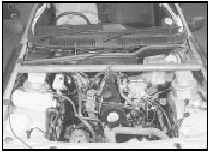
29.9b . . . which will support the engine
Attach the lifting
tackle to the engine lifting brackets on the
cylinder head. If using a support bar, the
engine may be lifted slightly by using the bar
as a lever before resting it on the wooden
blocks.
10 Support the front crossmember with a trolley jack, then unscrew the bolts securing the crossmember to the underbody (see illustration).
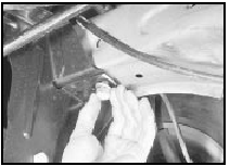
29.10 Unscrew the front crossmember securing bolts
11 Lower the crossmember just enough to give sufficient clearance to remove the sump (see illustrations).
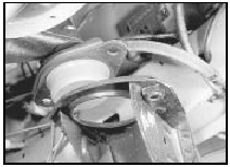
29.11a Lower the suspension . . .
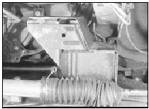
29.11b . . . to give sufficient clearance for sump removal
12 Unscrew the twenty-three securing bolts and withdraw the sump (see illustration).
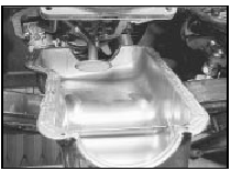
29.12 Unscrew the securing bolts and withdraw the sump
If the sump is stuck, carefully tap it sideways to free it. Do not prise between the mating faces.
Note that if the engine has been removed, it is preferable to keep the engine upright until the sump has been removed to prevent sludge from entering the engine internals.
13 Recover the gaskets and sealing strips.
14 Thoroughly clean the mating faces of the cylinder block and sump.
Refitting
15 Commence refitting by applying sealing
compound (available from a Ford dealer) to
the corners of the front and rear rubber
sealing strip locations in the cylinder block,
then press the sealing strips into the grooves
in the rear main bearing cap and the
crankshaft front oil seal housing (see
illustrations).
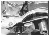
29.15a Apply sealing compound . . .
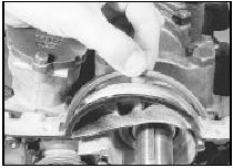
29.15b . . . then fit the rubber sealing strips
16 Apply a little sealing compound to the mating face of the cylinder block, then place the sump gaskets in position, ensuring that the end tabs locate correctly beneath the rubber sealing strips (see illustration).
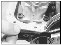
29.16 Locate the sump gasket end tabs beneath the rubber sealing strips
17 Locate the sump on the gaskets and loosely fit the securing bolts.
18 Tighten the bolts in the correct sequence (see illustration)
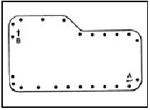
29.18 Sump bolt tightening sequence - refer to text
noting the two stages given in the Specifications. Tighten to the first stage in a clockwise sequence starting at point “A”, then tighten to the second stage in a clockwise sequence starting at point “B”.
Tighten to the third stage after the engine has been running for twenty minutes.
19 If the engine is in the vehicle proceed as follows.
20 Carefully lift the crossmember with the jack, then refit the securing bolts and tighten to the specified torque.
21 Withdraw the jack, then lower the engine and remove the lifting tackle.
22 Where applicable, refit the brake lines to the crossmember.
23 Ensure that the front wheels are pointing straight ahead and that the steering wheel is centred, then reconnect the intermediate shaft to the steering column. Secure the clamp plate with the bolt.
24 Refit the engine mounting bolts and tighten to the specified torque.
25 Refit the starter motor.
26 Lower the vehicle to the ground.
27 Ensure that the sump drain plug is fitted, then fill the engine with the correct quantity and grade of oil. If necessary, renew the oil filter before filling the engine with oil.
28 Reconnect the battery negative lead.
29 Start the engine and check for leaks around the sump, and where applicable the oil filter. When the engine is started, there may be a delay in the extinguishing of the oil pressure warning lamp while the system pressurises.
30 Run the engine for twenty minutes then stop the engine and tighten the sump bolts to the third stage given in the Specifications, starting at the point “A” shown and working clockwise.
31 Check the oil level.
32 Dispose of any old engine oil safely. Do not pour it down a drain - this is illegal and causes pollution.
See also:
Ignition system component check (Every 6000 miles or 6 months)
1 Where applicable, remove the distributor
cap and thoroughly clean it inside and out
with a dry lint-free cloth. Examine the four HT
lead segments inside the cap. If the segments
appear badly bur ...
Wiring diagrams
Notes, tables, wire colours and key to wiring diagrams. Models up to 1987
Notes, tables, wire colours and key to wiring diagrams. Models up to 1987
Key to wiring diagrams (continued). Models up to ...
Cab interior trim panels (P100 models) - removal and refitting
Side trim panel
1 Remove the rear pillar trim panel.
2 Remove the side trim panel by prising out
the four expander pins from the clips, then
pulling out the clips and withdrawing the
panel.
3 Re ...
