Cylinder head - removal and refitting (engine removed)
Note: New cylinder head bolts, a new cylinder head gasket, a new timing chain tensioner plunger assembly, a new upper timing chain cover gasket, and a new camshaft cover gasket and reinforcing sleeve sealing rings, must be used on refitting.
Removal
1 With the manifolds removed, proceed as
follows.
2 Unscrew the eleven bolts and four nuts, and remove the camshaft cover. Recover the gasket.
3 Unscrew the four securing bolts and three studs, and remove the upper timing chain cover. Note the locations of the studs to aid refitting.
4 Using a spanner on the crankshaft pulley, turn the crankshaft to bring No 1 piston to the firing point. With No 1 piston at the firing point, the timing marks on the camshaft sprockets should be pointing away from each other, and should be approximately level with the top edge of the cylinder head. Timing notches are provided in the camshaft sprockets, and corresponding paint marks are provided on the outside edges of the sprockets (see illustration).
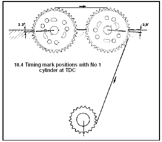
18.4 Timing mark positions with No 1 cylinder at TDC
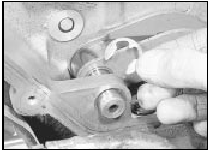
5 Hold the inlet camshaft sprocket stationary using an improvised tool similar to that shown then unscrew the camshaft sprocket bolt and remove the distributor rotor shaft (see illustration).
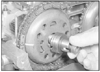
18.5 Removing the inlet camshaft sprocket bolt and the distributor rotor
shaft
6 Repeat the procedure given in the previous paragraph for the exhaust camshaft, but note that a spacer is fitted in place of the distributor rotor shaft.
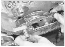
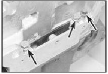
7 Squeeze the upper timing chain guide securing lugs together, using pliers if necessary, and withdraw the guide from the plate at the front of the cylinder head (see illustrations).
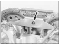
18.7a Upper timing chain guide securing lugs (arrowed)
18.7b Removing the upper timing chain guide
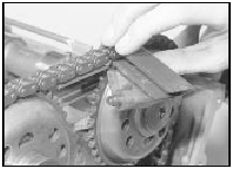
8 Mark the position of the timing chain in relation to the camshaft sprockets, so that the chain can be refitted in precisely its original position (ie, make alignment marks between each sprocket and a corresponding link in the chain), then slide the camshaft sprockets from the camshafts. Withdraw the sprockets and lay the timing chain over the exhaust side of the timing case, having eliminated the slack in the chain. Secure the chain using a cable-tie through two of the chain links, to prevent it from dropping off the crankshaft sprocket.
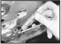
9 Using a suitable pair of pliers, extract the circlip from the chain tensioner arm pivot pin, taking care not to drop it into the timing case, then withdraw the pivot pin from the tensioner arm (see illustrations).
18.9a Removing the chain tensioner arm pivot pin circlip
18.9b Withdrawing the pivot pin from the chain tensioner arm
If the pivot pin proves difficult to withdraw, an M6 bolt can be screwed into its end to facilitate removal.
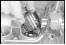
10 Lift the chain tensioner arm from the timing case.
11 Lift the chain tensioner plunger assembly from the cylinder head, and discard it (see illustration).
18.11 Lifting the chain tensioner plunger assembly from the cylinder head
Warning: Take care when removing the plunger assembly, as there is a risk of injury if the piston flies out.
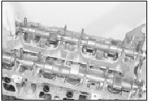
12 Take note of the markings on the camshaft bearing caps, then progressively unscrew the bearing cap securing nuts.
13 Remove the bearing cap securing nuts, then lift off the camshaft oil spray bars (see illustration), and the timing chain guide plate.
18.13 Lifting off a camshaft oil spray bar
14 Lift off the bearing caps, and then lift out the two camshafts (see illustrations). Note that the inlet camshaft is normally identified by a green paint mark. If necessary, identify the camshafts so that they can be refitted in their correct positions.
18.14a Lifting off a camshaft bearing cap
18.14b Lifting out the exhaust camshaft
15 Withdraw the cam followers from their locations in the cylinder head, keeping them in order so that they can be refitted in their original locations (see illustration). It is advisable to store the cam followers upright in an oil bath until they are to be refitted. Ensure that the depth of oil is sufficient to fully cover the cam followers.
18.15 Withdrawing a cam follower
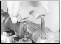
16 Working at the front of the cylinder head, unscrew the three small M8 cylinder head bolts which are accessible through the timing case (see illustration).
18.16 M8 cylinder head bolts (arrowed) located at front of cylinder head
17 Working in the reverse order to that shown for the tightening sequence, progressively loosen the remaining cylinder head bolts and withdraw them from the cylinder head.
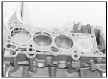
18 Lift the cylinder head from the block. If the cylinder head is stuck, tap it free with a softfaced mallet. Do not insert a lever into the joint between the cylinder head and block, as this may result in damage to the mating faces.
Place the cylinder head on blocks of wood to prevent damage to the valves.
19 Recover the gasket, and the locating dowels if they are loose, noting the positions of the locating dowels.
Refitting
20 Commence refitting as follows.
21 Turn the crankshaft so that No 1 piston is approximately 20.0 mm (0.8 in) before TDC.
This precaution will prevent possible contact between the valves and pistons.
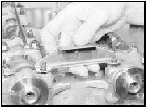
22 Make sure that the mating faces of the cylinder block and cylinder head are perfectly clean, then refit the locating dowels (where applicable) and locate a new gasket over the dowels. Note that the gasket can only fit in one position (see illustration). Do not use jointing compound.
18.22 Fitting a new cylinder head gasket
23 Lower the cylinder head onto the gasket, making sure that the locating dowels engage.
24 Oil the threads of the new main cylinder head bolts, and insert them into their locations in the cylinder head.
25 Tighten the bolts in the order shown (see illustrations) in the four stages given in the Specifications.
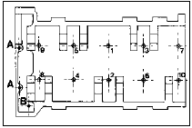
18.25a Cylinder head bolt tightening sequence
A Long M8 bolt B Short M8 bolt
18.25b Tightening a cylinder head bolt using an angle gauge
26 Insert the three smaller M8 cylinder head bolts through the top of the timing case and tighten them to the specified torque. Note that new bolts must be used, and that they should be of the latest type, with hexagonal heads (see illustration).
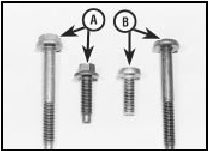
18.26 Use new M8 (auxiliary) cylinder head bolts with hexagonal heads (A),
not earliertype Torx bolts (B)
27 Lubricate the cam follower bores in the cylinder head, and the cam followers themselves, then insert the cam followers into their original locations in the cylinder head.
28 Lubricate the camshaft bearing surfaces in the cylinder head, and the bearing caps.
29 Lubricate the surfaces of the camshafts, then carefully lay the camshafts in their original positions in the cylinder head.
Position the camshafts with the slots in their front ends pointing away from each other.
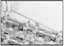
30 Fit and tighten the bearing caps L1, L3, L5, R1, R3, and R5 in the sequence shown (see illustration) then lay the camshaft oil spray bars and the timing chain guide plate in position over the studs (see illustrations).
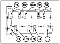
18.30a Camshaft bearing cap tightening sequence (see text)
18.30b Camshaft oil spray bars correctly fitted
18.30c Fitting the timing chain guide plate
31 Carefully tighten the bearing cap securing nuts by hand in the following sequence to lower the camshafts into position. Continue to tighten the nuts in the sequence given, in small amounts, until the bearing caps contact the cylinder head.
1 Tighten the nuts for bearing caps L1 and R1 by half-a-turn (180º) 2 Tighten the nuts for bearing caps L5 and R5 by half-a-turn (180º) 3 Tighten the nuts for bearing caps L3 and R3 by half-a-turn (180º) 32 Fit bearing caps L2, L4, R2 and R4, and tap them into position on the cylinder head using light taps from a soft-faced mallet.
Tighten the securing nuts evenly by hand.
33 Tighten all the bearing cap nuts to the
specified torque in half-turn stages, using the
following sequence:
1 L1 and R1
2 L5 and R5
3 L3 and R3
4 L2 and L4
5 R2 and R4
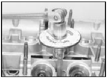
34 Fit a new chain tensioner plunger
assembly to the housing in the cylinder head
with the piston uppermost. Before fitting the
new plunger assembly, take note of the
position of the piston (see illustration). The
assembly is normally supplied with the piston
protruding slightly from the cylinder, or slightly
below the top surface of the cylinder (“A”). If
the new assembly is supplied with the piston
partially unlatched (“B”), or fully unlatched
with the latching ring visible (“C”), it must not
be used (see illustration).
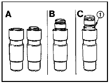
18.34 Timing chain tensioner plunger assembly
A Piston retracted - plunger assembly useable B Piston partially unlatched - discard plunger assembly C Latching ring (1) visible - discard plunger assembly
Warning: Take care when installing the plunger assembly, as there is a risk of injury if the piston flies out.
35 Locate the chain tensioner arm in position, then insert the pivot pin, and secure it with the circlip. Take care not to drop the circlip into the timing-case.
36 Release the cable-tie securing the timing chain (if used), and lay the chain over the exhaust camshaft sprocket, aligning the marks made previously on the chain and sprocket, so that the timing chain is taut on the exhaust side of the engine.
37 Fit the sprocket to the exhaust camshaft, with the camshaft in the TDC position (ie with the exhaust camshaft sprocket timing mark in line with the top edge of the cylinder head, pointing to the exhaust side of the engine - see paragraph 4. If necessary, use a pair of pliers on one of the unmachined sections of the camshaft to turn the camshaft to the TDC position. Take care not to damage the machined surfaces of the camshaft.
38 With the sprocket fitted, fit the spacer to the end of the camshaft, and tighten the securing bolt finger-tight (see illustration).
18.38 Spacer and sprocket securing bolt fitted to end of camshaft, with
camshaft in TDC position (timing marks arrowed)
39 Lay the timing chain over the inlet camshaft sprocket, aligning the marks made previously on the chain and the sprocket.
40 Fit the sprocket to the inlet camshaft, with the camshaft in the TDC position (ie with the inlet camshaft sprocket timing mark in line with the top edge of the cylinder head, pointing to the inlet side of the engine - see paragraph 4). Again, turn the camshaft if necessary to enable the sprocket to be fitted.
41 With the sprocket fitted, fit the distributor rotor shaft to the end of the camshaft, and tighten the securing bolt finger-tight. Note that it is acceptable for the timing chain to sag slightly between the two pulleys.
42 Fit a new upper timing chain guide to the plate at the front of the cylinder head.
43 Turn the crankshaft clockwise until the inlet camshaft begins to turn.
44 If the chain tensioner plunger piston protrudes from the cylinder, unlatch the piston by pressing the chain tensioner arm down by hand.
45 If the plunger piston is below the top surface of the cylinder, a tool similar to that shown (see illustration)
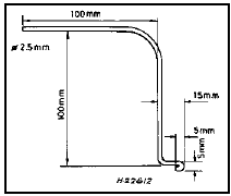
18.45 Fabricated tool used to unlatch tensioner plunger piston
must be fabricated to unlatch the piston. It is suggested that a 2.5 mm diameter welding rod is used to manufacture the tool. Use the tool to release the piston as follows.
46 Carefully lift the chain tensioner arm with a screwdriver, and insert the tool between the tensioner arm and the piston. Remove the screwdriver, and release the piston by pressing the tensioner arm down by hand.
Carefully withdraw the tool once the piston has been released.
47 Tighten the camshaft sprocket securing bolts to the specified torque, holding the sprockets stationary as during removal.
48 Turn the crankshaft clockwise through two complete revolutions, and check that the timing marks on the camshaft sprockets are still aligned with the top face of the cylinder head as described in paragraph 4.
49 Turn the crankshaft clockwise through another complete revolution, and check that the timing marks on the camshaft sprockets are facing each other, directly in line with the top face of the cylinder head.
50 If the timing marks do not align as described, the timing chain has been incorrectly fitted (probably one chain link away from the correct position on one of the camshaft sprockets), and the chain should be removed from the sprockets and refitted again in the correct position as described previously.
51 Inspect the oil seal in the upper timing chain cover. If the oil seal is in good condition, the cover can be refitted as follows, but if the seal is damaged, or has been leaking, a new seal should be fitted to the cover. If necessary, carefully prise the old oil seal from the cover using a screwdriver, and drive in the new seal using a suitable metal tube. Make sure that the seal lip faces into the engine.
Take care not to damage the timing chain cover.
52 Fit the upper timing chain cover using a new rubber gasket. Great care must be taken to avoid damage to the oil seal when passing the seal over the end of the inlet camshaft.
Careful manipulation will be required (possibly using a thin feeler blade) to avoid damage to the oil seal sealing lip. Note that the oil seal should be fitted dry.
53 Refit the timing chain cover securing bolts and studs in their original locations, and tighten them to the specified torque (see illustration).
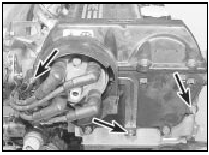
18.53 Upper timing chain cover securing stud locations (arrowed)
54 Remove the reinforcing sleeves from the camshaft cover, and renew the rubber sealing rings. Note that the four short reinforcing sleeves fit at the front of the cover (see illustration).
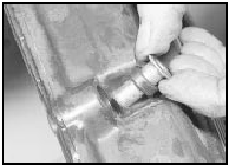
18.54 Fitting a camshaft cover reinforcing sleeve and sealing ring
55 Refit the camshaft cover using a new gasket, and tighten the securing bolts and studs to the specified torque.
Cylinder head - dismantling and reassembly
Note: A valve spring compressor will be required during this procedure. New valve stem oil seals should be used on reassembly.
1 Proceed as described in Chapter 2, Part C, noting the following points: a) Ignore the references to removing and refitting the camshaft.
b) Double valve springs are used on all the valves (see illustration).
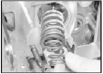
19.1 Withdrawing the double valve springs from the cylinder head
Cylinder head - inspection and renovation
1 Refer to Chapter 2, Part A, noting the
following points:
a) Valve and valve seat cutting and
regrinding can be carried out using
conventional tools.
b) The cylinder head cannot be resurfaced, and if the surface distortion exceeds the specified limits, the cylinder head must be renewed.
See also:
Seats - removal and refitting
Front seat
1 Slide the seat fully forwards, and on seats
with height adjustment unhook the tension
spring from the rear crosstube. Where
applicable, disconnect the wiring from the
seat heating pa ...
Specifications
General
Engine type . . . . . . . . . . . . . . . . . . . . . . . . . . . . . . . . . .
. . . . . . . . . . . . . Four-cylinder, in-line overhead camshaft
Capacity:
1.1 litre . . . . . . . . . . ...
Engine - reassembly
Note: Ensure that all necessary new oil seals
and gaskets have been obtained before
starting the reassembly procedure.
OHV engines
1 With everything clean, commence
reassembly by oiling the bores ...
