Front disc caliper - removal, overhaul and refitting
Caution: Refer to the precautions in Section 1.
Removal
1 Apply the handbrake, loosen the relevant
roadwheel nuts, then jack up the front of the
vehicle and support on axle stands. (see
“Jacking and Vehicle Support”). Remove the
roadwheel. On P100 models, mark the
position of the roadwheel in relation to one of
the wheel studs before removal.
2 Remove the brake fluid reservoir cap and secure a piece of polythene over the filler neck with a rubber band, or by refitting the cap. This will reduce the loss of fluid during the following procedure.
3 Disconnect the flexible fluid hose from the rigid brake pipe under the wing of the vehicle, or alternatively unscrew the flexible hose from the union on the caliper. Take care not to twist the hose, and plug the open ends to prevent fluid loss and dirt ingress.
4 Remove the disc pads.
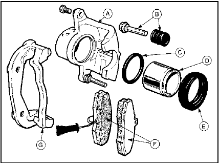
5 On models fitted with Girling calipers (1.3 and early 1.6 litre models) (see illustration),

6.5 Exploded view of Girling front disc caliper
A Caliper
B Guide pin and dust boot
C Piston seal
D Piston
E Dust-excluding seal
F Disc pads
G Caliper carrier bracket
unscrew and remove the bolt from the lower caliper guide pin, while holding the pin stationary with a spanner, then remove the caliper.
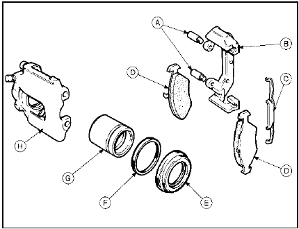
6 On models fitted with Teves calipers (later 1.6, 1.8 and 2.0 litre models) (see illustration), remove the caliper from the vehicle.

6.6 Exploded view of Teves front disc caliper
A Guide bolts
B Caliper carrier bracket
C Caliper retaining clip
D Disc pads
E Dust-excluding seal
F Piston seal
G Piston
H Caliper
7 If required, the caliper carrier bracket can be unbolted and removed from the hub carrier.
Overhaul
8 Brush away all external dirt and dust, but
take care not to inhale any dust as it may be
injurious to health.
9 Pull the dust-excluding rubber seal from the end of the piston.
10 Apply air pressure to the fluid inlet union, and eject the piston. Only low air pressure is required for this, such as is produced by a foot-operated tyre pump. Position a thin piece of wood between the piston and caliper body to prevent damage to the end face of the piston in the event of its being ejected suddenly.
11 Using a suitable pointed instrument, prise the piston seal from the groove in the cylinder bore. Take care not to scratch the surface of the bore.
12 Clean the piston and caliper body with methylated spirit and allow to dry. Examine the surfaces of the piston and cylinder bore for wear, damage and corrosion. If the piston surface alone is unserviceable, a new piston must be obtained, along with seals. If the cylinder bore is unserviceable, the complete caliper must be renewed. The seals must be renewed regardless of the condition of the other components.
13 Coat the piston and seals with clean brake fluid, then manipulate the piston seal into the groove in the cylinder bore.
14 Push the piston squarely into its bore.
15 Fit the dust-excluding rubber seal between the piston and caliper, then depress the piston fully.
Refitting
16 Refit the caliper and where applicable the
carrier bracket by reversing the removal
operations. Tighten the mounting bolts to the
specified torque.
17 On P100 models, when refitting the roadwheel align the previously made marks on the roadwheel and wheel stud.
18 On completion, bleed the front brake circuit.
See also:
Tailgate wiper motor - removal and refitting
Removal
1 Disconnect the battery and remove the
wiper arm/blade assembly.
2 Remove the pivot shaft nut, spacer and
outer seals.
3 Open the tailgate and remove the trim panel
(refer to Chapter 11 ...
Exhaust system check (Every 12 000 miles or 12 months)
With the vehicle raised on a hoist or
supported on axle stands (see “Jacking and
Vehicle Support”), check the exhaust system
for signs of leaks, corrosion or damage and
check the rubber mountings ...
Internal connection details, all models continued
Internal connection details, all models continued ...
