Crankshaft and main bearings - removal and refitting
Note: A new crankshaft rear oil seal and a new rear oil seal housing gasket should be used on refitting.
Removal
1 With the engine removed from the vehicle,
remove the timing chain and crankshaft
sprocket, and the flywheel/driveplate.
2 Remove the pistons and connecting rods. If no work is to be done on the pistons and connecting rods, there is no need to push the pistons out of the cylinder bores.
3 Unbolt the crankshaft rear oil seal housing, and remove it from the rear of the cylinder block. Recover the gasket.
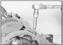
4 Unscrew the two securing bolts, and remove the sump mounting plate from the front of the cylinder block (see illustration).

30.4 Unscrewing a sump mounting plate securing bolt
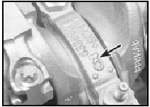
5 Check the main bearing caps for identification marks, and if necessary, use a centre-punch to identify them (see illustration).

30.5 Main bearing cap identification mark (arrowed)
6 Before removing the crankshaft, check that the endfloat is within the specified limits by inserting a feeler blade between the centre crankshaft web and one of the thrustwashers (the thrustwashers are fitted to the crankcase, not the bearing cap). This will indicate whether or not new thrustwashers are required.
7 Unscrew the bolts, and tap off the main bearing caps complete with bearing shells.
8 Lift the crankshaft from the cylinder block, and remove the rear oil seal if it is still in place on the crankshaft.
9 Extract the bearing shells, and recover the thrustwashers, keeping them identified for location.
Refitting
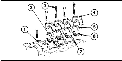
10 Commence refitting as follows (see
illustration).

30.10 Crankshaft main bearings and associated components
1 Bearing cap
2 Thrustwasher
3 Stud for oil baffle
4 Identification markings
5 Bearing shell without oil groove
6 Bearing shell with oil groove
7 Bearing seat in cylinder block
11 Wipe the bearing shell locations in the crankcase, and the crankshaft journals with a soft non-fluffy rag.
12 If the old main bearing shells are to be renewed (not to do so is a false economy, unless they are virtually new) fit the five upper halves of the main bearing shells to their locations in the crankcase.
13 Fit the thrustwashers to the centre main bearing location, using a little grease to retain them if necessary. The oil grooves in the thrustwashers must face outwards (ie facing the crankshaft webs). Note that where standard thrustwashers have been fitted in production, the centre main bearing is unmarked. If oversize (0.38 mm) thrustwashers have been fitted, the centre main bearing will carry a yellow paint mark.
14 Lubricate the crankshaft journals and the upper and lower main bearing shells with clean engine oil, then carefully lower the crankshaft into the crankcase.
15 Lubricate the crankshaft main bearing journals again, and then fit the main bearing caps in their correct locations, with the arrows on the caps pointing to the front of the engine.
16 Fit the main bearing cap bolts, noting that the studded bolts secure bearing caps Nos 3 and 5.
17 Lightly tighten all the securing bolts, then progressively tighten all bolts to the specified torque.
18 Check that the crankshaft rotates freely.
Some stiffness is to be expected with new components, but there must be no tight spots or binding.
19 Check that the crankshaft endfloat is within the specified limits by inserting a feeler blade between the centre crankshaft web and the thrustwashers.
20 Refit the sump mounting plate to the front of the cylinder block, and tighten the securing bolts to the specified torque.
21 Carefully wind a thin layer of tape around the rear edge of the crankshaft, to protect the oil seal lips as the rear oil seal is installed.
22 Refit the crankshaft rear oil seal housing, using a new gasket, and tighten the securing bolts to the specified torque.
23 Ideally, the new oil seal should be installed using a tool similar to that used for fitting the crankshaft rear oil seal. A suitable tool can be improvised using a metal tube of suitable diameter, a metal disc or flat bar, and two flywheel bolts. Draw the seal into position using the two flywheel bolts. Make sure that the seal lip faces into the engine.
24 With the oil seal installed, carefully pull the tape from the edge of the crankshaft.
25 Refit the pistons and connecting rods.
26 Refit the flywheel/driveplate, and the timing chain and crankshaft sprocket.
Crankshaft and bearings - examination and renovation
1 Proceed as described in Chapter 2, Part A, noting the following.
2 Production bearing undersizes are
indicated as follows:
Yellow or red paint marks on crankshaft -
standard-diameter main bearing journals.
Green line on crankshaft front counterweight - main bearing journals 0.25 mm undersize.
Green spot on counterweight - big-end bearing journals 25 mm undersize.
Initial start-up after overhaul or major repair
1 Refer to Chapter 2, Part A, but note that when the engine is first started, a metallic tapping noise may be heard. This is due to the timing chain tensioner plunger assembly taking time to pressurise with oil, resulting in a temporarily slack chain. The noise should stop after a short time, once oil pressure has built up.
CVH engines
The 1.6 litre CVH engine was introduced in September 1991, to replace the 1.6 litre SOHC engine used previously in the Sierra range. The engine is broadly similar to the 1.8 litre (R2A type) CVH engine described below. The main differences are outlined in the following paragraphs.
The centre main bearing is fitted with thrustwashers to control crankshaft endfloat, instead of a flanged bearing shell.
See also:
Air Charge Temperature (ACT) sensor - removal and refitting
Removal
1 The ACT sensor is screwed into the CFI
unit.
2 Disconnect the battery negative lead.
3 Remove the air cleaner assembly.
4 Disconnect the ACT sensor wiring plug (see
illustration).
1 ...
Alternator - removal and refitting
Removal
1 Disconnect the battery leads.
2 Disconnect the multi-plug, or disconnect
the wires from their terminals on the rear of
the alternator, noting their locations (as
applicable), then slack ...
Cylinder head - dismantling and reassembly
Note: A valve spring compressor will be
required during this procedure. New valve
stem oil seals should be used on reassembly.
Dismantling
1 With the cylinder head removed, remove
the camshaft.
...
