Pistons and connecting rods - examination and renovation
1 Examine the pistons for ovality, scoring, and scratches. Check the connecting rods for wear and damage. The connecting rods carry a letter indicating their weight class; all the rods fitted must be of the same class.
2 The gudgeon pins are an interference fit in the connecting rods, and if new pistons are to be fitted to the existing connecting rods, the work should be carried out by a Ford dealer who will have the necessary tooling. Note that the oil splash hole in the connecting rod must be located on the right-hand side of the piston (the arrow on the piston crown faces forwards).
3 If new rings are to be fitted to the existing pistons, expand the old rings over the top of the pistons. The use of two or three old feeler blades will be helpful in preventing the rings dropping into empty grooves. Note that the oil control ring is in three sections.
4 Before fitting the new rings to the pistons, insert them into the cylinder bore and use a feeler blade to check that the end gaps are within the specified limits (see illustration).
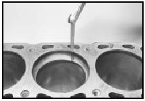
33.4 Checking a piston ring gap at the top of the cylinder bore
5 Clean out the piston ring groove using a piece of old piston ring as a scraper. Be careful not to scratch the aluminium surface of the pistons. Protect your fingers - piston ring edges are sharp.
6 Fit the oil control ring sections with the spreader ends abutted opposite the front of the piston. The side ring gaps should be 25 mm (1.0 in) either side of the spreader gap. Fit the tapered lower compression ring with the “TOP” mark towards the top of the piston and the gap 150º from the spreader gap, then fit the upper compression ring with the gap 150º on the other side of the spreader gap. Note that the compression rings are coated with a molybdenum skin which must not be damaged.
Note also that the compression rings are made of cast iron, and will snap if expanded too far.
See also:
Diagram 4b: 1986-on KE-Jetronic fuel injection
Diagram 4b: 1986-on KE-Jetronic fuel injection For starting and charging
circuits see Diagram 1a ...
Specifications
General
System type . . . . . . . . . . . . . . . . . . . . . . . . . . . . . . . . . .
. . . . . . . . . . . . Multi-point electronic fuel injection
Application . . . . . . . . . . . . . . . . . ...
Underbonnet lamp - removal, refitting and bulb renewal
1 Disconnect the battery negative lead.
Removal and refitting
2 Detach the wiring connector at the left-hand
bonnet hinge, and attach a length of string to
the end of the wire running from the lam ...
