Rear brake backplate (drum brakes) - removal and refitting
Caution: Refer to the precautions in Section 1.
Saloon, Hatchback and Estate
models
1 Remove the rear brake shoes.
2 Disconnect the handbrake cable from the backplate by extracting the U-clip.
3 Remove the wheel cylinder.
4 Remove the driveshaft but do not refit the securing bolts to the backplate.
5 Remove the backplate.
6 If required, prise out the handbrake stop button.
7 Refitting is a reversal of removal.
P 100 models
Note: When refitting the backplate, a new rear
hub nut and driveshaft O-ring must be used.
8 Proceed as described in paragraphs 1 to 3 inclusive.
9 Remove the driveshaft.
10 Relieve the staking on the rear hub nut, and using a 50 mm socket and a suitable extension bar, unscrew the nut. Note that the nut is extremely tight.
11 Pull off the hub.
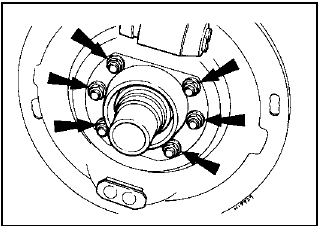
12 Unscrew the six retaining nuts and remove the backplate and the oil baffle (see illustration).

11.12 Brake backplate and oil baffle retaining nuts
13 If required, prise out the handbrake stop button.
14 Refitting is a reversal of removal, bearing in mind the following points.
15 When refitting the backplate and the oil baffle, coat the area of the oil baffle shown (see illustration - Chapter 9) with sealant to Ford spec SPM-4G-9112-F, then refit the baffle and the backplate to the axle, tightening the six securing nuts to the specified torque.
16 Use a new rear hub nut, and tighten to the specified torque. Stake the nut into the groove in the axle tube after tightening.
17 Refit the driveshaft, using a new O-ring.
See also:
Accelerator pedal - removal and refitting
The procedure is the same as described in
Part A of this Chapter for carburettor models. ...
Front anti-roll bar - removal and refitting
Removal
1 The anti-roll bar is used in conjunction with
the forged type suspension lower arm.
2 Jack up the front of the car and support it
on stands (see “Jacking and Vehicle Support”).
3 Where ...
Fuel tank - removal and refitting
The procedure is as described in Part A of
this Chapter for carburettor engines. ...
