Fluid reservoir (ABS) - removal and refitting
Note: New seals must be used between the reservoir and the hydraulic unit on reassembly.
Caution: Refer to the
precautions in Section 1.
Removal
1 Disconnect the battery negative lead.
2 Depressurise the hydraulic system by pumping the brake pedal at least 20 times, or until it becomes hard.
3 Disconnect the wiring multi-plugs from the reservoir cap and remove the cap.
4 Unscrew the reservoir securing screw, and remove the securing clip, noting that the clip also supports the clutch cable (see illustration).
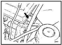
15.4 Reservoir securing clip (arrowed) also supports clutch cable - ABS
5 Prepare a suitable container to collect the fluid as the hydraulic unit is drained, then remove the securing spring clip and disconnect the low pressure fluid hose from the pump (see illustrations). Allow the fluid to drain out of the hose into the container. If fluid is accidentally spilt on the paintwork, wash off immediately with cold water.
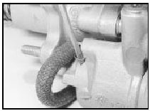
15.5a Remove the securing spring clip . . .
15.5b . . . and disconnect the low pressure fluid hose - ABS
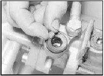
6 Pull the reservoir out of the seals on the hydraulic unit and remove it (see illustration).
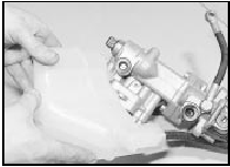
15.6 Removing the fluid reservoir from the hydraulic unit - ABS
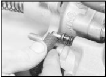
7 Note the spigot locating bush on the rear hydraulic unit inlet, which may stay in the hydraulic unit or may come out with the reservoir (see illustration).
15.7 Removing the spigot locating bush from the rear hydraulic unit inlet -
ABS
Refitting
8 Refitting is a reversal of removal, but use
new seals between the reservoir and the
hydraulic unit.
9 On completion, bleed the complete hydraulic system and check for leaks around all disturbed components.
See also:
Ford Sierra Service Manual
...
Ignition systems
The ignition system is divided into two circuits, low tension
(primary) and high tension (secondary). The low tension circuit consists of the
battery, ignition switch, primary coil windings and th ...
Bonnet - removal and refitting
Removal
1 Support the bonnet in its open position,
and place protective covers (old rags or
cardboard) beneath the corners of the bonnet,
and over the front wings to prevent damage to
the paintwo ...
