Steering column - removal and refitting
Removal
1 Set the front wheels in the straight-ahead
position.
2 Disconnect the battery negative lead.
3 Remove the driverís side lower facia trim panels.
4 Remove the screws and withdraw the steering column upper and lower shrouds (see illustrations).
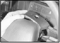
24.4a Remove the steering column upper shroud . . .
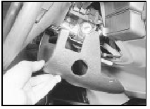
24.4b . . . and lower shroud
5 Unscrew the two crosshead screws and withdraw the two combination switches from the column.
6 Remove the screw from the bonnet release lever and remove the lever.
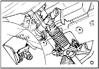
7 Working in the engine compartment, unscrew the bolt securing the intermediate shaft to the inner column, swivel the clamp plate to one side, and disconnect the intermediate shaft (see illustration).
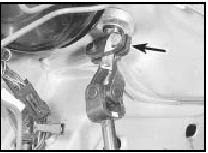
24.7 Intermediate shaft-to-inner column universal joint and clamp plate
(arrowed)
8 Unscrew the nuts securing the outer column to the facia.
9 Disconnect the multi-plugs and withdraw the column assembly upwards (see illustration).
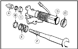
24.9 Steering column components
A Direction indicator cam
B Thrustwashers
C Bearings
D Outer column
E Spring
F Inner column
Refitting
10 Refit the column assembly in the car and
tighten the upper mounting nuts lightly.
Loosen the mounting pinch-bolt.
11 Temporarily fit the upper column shroud and adjust the position of the steering column until there is a gap of 5.0 mm (0.2 in) between the shroud and the facia (see illustration).
24.11 Upper column shroud-to-facia gap adjustment
X = 5.0 mm (0.2 in)
12 Tighten the pinch-bolt and the mounting nuts and remove the upper column shroud.
13 With the steering wheel in the straight-ahead position, reconnect the intermediate shaft and tighten the clamp plate bolt to the specified torque.
14 Refit the bonnet release lever and combination switches and reconnect the multi-plugs.
15 Refit the steering column shrouds and trim panels.
16 Reconnect the battery negative lead.
See also:
Engine/transmission - reconnection and installation
1 This is a direct reversal of removal and
separation from the transmission. Take care
not to damage the radiator or front wings
during installation.
Reconnection
2 Make sure that the engine adap ...
Steering column - removal, overhaul and refitting
Removal
1 Disconnect the battery negative terminal.
2 Turn the ignition key and rotate the steering
wheel to bring the front roadwheels to the
straight-ahead position.
3 Working within the engine ...
Fuel pump - removal and refitting
Removal
1 The fuel pump is integral with the fuel level
sender unit in the fuel tank (see illustration).
7.1 Integral fuel level sender unit/fuel pump - 1.4 CFI engine
A Fuel pump B Sender unit
...
