Front wheel alignment - checking and adjusting
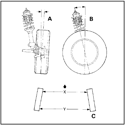
1 Front wheel alignment is defined by camber, castor steering axis inclination and toe setting. The first three factors are determined in production; only toe can be adjusted in service. Incorrect toe will cause rapid tyre wear.
2 Toe is defined as the amount by which the distance between the front wheels, measured at hub height, differs from the front edges to the rear edges. If the distance between the front edges is less than that at the rear, the wheels are said to toe-in; the opposite case is known as toe-out.
3 To measure toe, it will be necessary to obtain or make a tracking gauge. These are available in motor accessory shops, or one can be made from a length of rigid pipe or bar with some kind of threaded adjustment facility at one end. Many tyre specialists will also check toe free, or for a nominal sum.
4 Before measuring toe, check that all steering and suspension components are undamaged and that tyre pressures are correct. The vehicle must be at approximately kerb weight, with the spare wheel and jack in their normal positions and any abnormal loads removed.
5 Park the vehicle on level ground and bounce it a few times to settle the suspension.
6 Use the tracking gauge to measure the distance between the inside faces of the front wheel rims, at hub height, at the rear of the front wheels. Record this distance; call it measurement “Y” (see illustration).

34.6 Front wheel alignment
A Camber B Castor C Toe setting For X and Y, see text
7 Push the vehicle forwards or backwards so that the wheels rotate exactly 180º (half a turn). Measure the distance between the front wheel rims again, this time at the front of the wheels. Record this distance; call it measurement “X”.
8 Subtract measurement “X” from measurement “Y”. If the answer is positive it is the amount of toe-in; if negative it is the amount of toe-out. Permissible values are given in the Specifications.
9 If adjustment is necessary loosen the tie-rod end locknuts and the outer bellows clips, then rotate each tie-rod by equal amounts until the setting is correct. Hold the tie-rod ends in their horizontal position with a spanner while making the adjustment.
10 Tighten the locknuts and outer bellows clips.
11 Provided the tie-rods have been adjusted by equal amounts the steering wheel should be central when moving straight-ahead. The amount of visible thread on each tie-rod should also be equal. If necessary refer to Section 23.
See also:
Heater matrix - removal and refitting
Removal
1 With the heater removed from the vehicle
as previously described, extract the two
securing screws and slide the matrix out of
the heater casing.
2 If further dismantling is necessary, c ...
Air cleaner element renewal (Every 24 000 miles or 2 Years)
Carburettor and Central Fuel
Injection (CFI) models
1 To remove the air cleaner lid undo and
remove the retaining screws or bolts on the
top face of the lid (see illustrations).
34.1a Removing ...
Radio/cassette player - removal and refitting
Standard fixing
1 Disconnect the battery negative lead.
2 Pull off the two control knob assemblies.
3 Release the trim panel by unscrewing the
two securing nuts from the control spindles.
Remove ...
