Fuel injectors and injector delivery pipes - removal and refitting
Note: Refer to the precautions at the end of Section 1 before proceeding. It is important to note that each injection supply pipe connection in the distributor head has a screw adjacent to it. These four screws are not for adjustment and must not be removed or have their settings altered. New O-ring seals must be used on refitting.
Removal
1 Disconnect the battery earth lead.
2 Detach the four supply pipes from the injectors, and use a rag to collect any spilled fuel.
3 Unscrew and remove the respective injector retaining bracket bolts, then withdraw the injectors and their O-ring seals (see illustration).
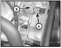
8.3 Injector fuel pipe union (A) and retaining bracket bolt (B)
4 The injector fuel delivery pipes can be removed by unscrewing and removing the four banjo bolts at the distributor head. Note the respective pipe connections as they are detached and remove the pipes complete with the plastic hoses and the injector harness. Do not separate the pipes or hoses from the injector harness.
5 Before reassembling the fuel delivery pipes, or the injectors, clean all pipe connections thoroughly and use new O-ring seals on the injectors. Use new seal washers on the banjo connections fitting two washers (one each side) per union. Do not overtighten the banjo bolts, or the washers may fracture.
Refitting
6 Refitting of the injectors and the fuel delivery
pipes is otherwise a reversal of the removal
procedure. On completion check that the pipes
and hoses are not distorted and when the
engine is restarted check for any signs of leaks.
See also:
Facia panels - removal and refitting
Models up to 1992
1 Note the locations of the facia panel
securing screws (see illustration).
43.1 Facia panel securing screw locations (arrowed)
A Upper facia panel
B Passenger side lower faci ...
Ford Sierra Service Manual
...
Fuel vapour separator (models from 1985) - removal and refitting
Caution: Refer to the
precautions in Section 1 before
proceeding.
Removal
1 On SOHC models, the vapour separator is
located on the left-hand side of the engine
compartment. On CVH models, the va ...
