Thermo-time switch - removal and refitting
Removal
1 Disconnect the battery negative lead.
2 Drain the cooling system as described in Chapter 1.
3 Raise the front of the car and support it on axle stands (see “Jacking and Vehicle Support”).
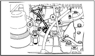
4 Disconnect the wiring multi-plug from the thermo-time switch located on the inlet manifold intermediate flange and accessible from under the car (see illustration).

18.4 Thermo-time switch (A) and temperature sensor (B) on the KE-Jetronic
system (viewed from under the car)
5 Unscrew the unit and remove it from its location.
Refitting
6 Refitting is a reversal of removal. Refill the
cooling system as described in Chapter 1.
See also:
Engine/transmission mountings - removal and refitting
Refer to Part A, Section 11. ...
Air Charge Temperature (ACT) sensor - removal and refitting
Removal
1 The air charge temperature sensor is
screwed into the inlet manifold (see
illustration).
14.1 Air charge temperature sensor - 1.6 EFI engine
A Wiring plug B Sensor
2 Disconnect the b ...
Throttle Position Sensor (TPS) - removal and refitting
Removal
1 Disconnect the battery negative lead.
2 Unclip and disconnect the sensor wiring
plug.
3 Remove the two securing screws, and
withdraw the sensor from the throttle valve
shaft (see illus ...
