Oil pump - dismantling, inspection and reassembly
Note: A new pressure relief valve plug and pick-up tube gasket will be required for reassembly.
Dismantling
1 If oil pump wear is suspected, check the
cost and availability of new parts and the cost
of a new pump. Examine the pump as
described in this Section and then decide
whether renewal or repair is the best course of
action.
2 Unbolt the pick-up tube and strainer.
Recover the gasket.
3 Unscrew the three securing bolts and remove the oil pump cover (see illustration).
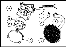
31.3 Exploded view of the oil pump
A Body
B Outer rotor
C Inner rotor
D Cover
E Strainer
F Pick-up tube
G Gasket
H Pressure relief valve
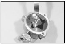
4 Mark the rotor faces so that the rotors can be refitted in their original positions, then lift the rotors from the pump body.
5 Remove the pressure relief valve plug by piercing it with a punch and levering it out, then withdraw the spring and plunger.
6 Thoroughly clean all parts in petrol or paraffin and wipe dry using a non-fluffy rag.
Reassembly and inspection 7 Commence reassembly by lubricating the relief valve plunger. Fit the plunger and spring.
8 Fit a new relief valve plug, flat side outwards and seat it with a drift until it is flush with the pick-up mating face.
9 Lubricate the rotors and fit them. Note the marks made when dismantling, if applicable.
10 The necessary clearances may now be checked using a machined straight edge (a good steel rule) and a set of feeler blades. The critical clearances are between the lobes of the centre rotor and convex faces of the outer rotor; between the outer and pump body; and between both rotors and the end cover plate (endfloat). The desired clearances are given in the Specifications (see illustrations).
31.10a Checking the oil pump outer rotorto- body clearance
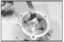
31.10b Checking the oil pump inner-toouter rotor clearance
11 Endfloat can be measured by placing a straight edge across the pump body and measuring the clearance between the two rotors and the straight edge using feeler blades (see illustration).
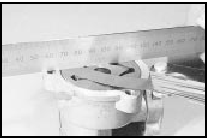
31.11 Checking the oil pump rotor endfloat
12 New rotors are only available as a pair. If the rotor-to-body clearance is excessive, a complete new pump should be fitted.
13 Refit the pump cover and tighten the securing bolts.
14 Fit the pick-up tube and strainer, using a new gasket.
15 Temporarily insert the driveshaft into the pump and make sure that the rotors turn freely.
16 Prime the pump before refitting.
See also:
Tailgate/boot lid/fuel filler flap release cable - removal and refitting
Removal
1 Operate the control lever to open the
tailgate/boot lid and the fuel filler flap (see
illustration).
14.1 Tailgate/boot lid/fuel filler flap control lever assembly
2 Remove the driver ...
General information
All models utilise a light alloy inlet manifold
which on carburettor models is coolant
heated to improve the atomisation of the
fuel/air mixture.
The exhaust manifold is of cast iron
construction ...
Thermostat - removal and refitting
1 Disconnect the battery negative lead.
2 Drain the cooling system.
3 Proceed as follows according to model:
SOHC models
4 Disconnect the radiator top hose and
expansion tank hose from the thermo ...
