Oil pump - dismantling, inspection and reassembly
1.8 litre (R2A type)
1 If oil pump wear is suspected, check the
cost and availability of new parts and the cost
of a new pump. Examine the pump as
described in this Section and then decide
whether renewal or repair is the best course of
action.
2 Using a suitable Torx socket, unscrew the seven securing bolts and remove the oil pump cover (see illustration).
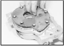
29.2 Remove the oil pump cover
3 Mark the rotor faces so that the rotors can be refitted in their original positions, then lift the rotors from the pump housing (see illustration).
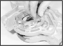
29.3 Lifting out the oil pump inner rotor
4 Unscrew the pressure relief valve plug and withdraw the spring and plunger (see illustration).
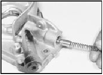
29.4 Unscrew the pressure relief valve plug and withdraw the spring and
plunger
5 Thoroughly clean all parts in petrol or paraffin and wipe dry using a non-fluffy rag.
6 Commence reassembly by lubricating the relief valve plunger. Fit the plunger and spring, and screw the plug into place.
7 Lubricate the rotors and fit them, observing the marks made when dismantling, if applicable.
8 The necessary clearances may now be checked using a machined straight-edge (such as a good steel rule) and a set of feeler blades. The critical clearances are between the lobes of the centre rotor and convex faces of the outer rotor; between the outer rotor and pump body; and between both rotors and the cover plate (endfloat). The serviceable clearances are given in the Specifications.
9 Endfloat can be measured by placing a straight-edge across the pump body and measuring the clearance between the two rotors and the straight-edge using feeler blades.
10 Refit the pump cover and tighten the securing bolts.
11 Prime the pump before refitting.
1.6 and 1.8 litre (R6A type) 12 The procedure is as described above but refer to the Specifications at the beginning of this Chapter for the rotor clearances.
See also:
Crankshaft rear oil seal - renewal
1 Remove the flywheel/driveplate.
2 Prise out the oil seal. If necessary, drill the
outer face of the oil seal and use self-tapping
screws and a pair of grips to withdraw the
seal (see illustratio ...
Idle speed and mixture adjustment (Every 6000 miles or 6
months)
Caution: Certain adjustment
points in the fuel system are
protected by “tamperproof”
caps, plugs or seals. In some
EEC countries (though not yet in the UK)
it is an offence to drive a vehicle wit ...
Interior trim panels - removal and refitting
Rear quarter trim panel
Removal
1 Unbolt the seat belt from its floor mounting.
2 Pass the belt buckle slide through the panel
aperture.
3 Pull the seat cushion and backrest forward.
4 Extract t ...
