Hydraulic unit pressure switch (ABS) - removal and refitting
Note: To remove the pressure switch from the hydraulic unit in situ, Ford tool No 12-008 or a locally made equivalent will be required. The switch may be removed without special tools after removing the hydraulic unit complete or the pump above. A new O-ring must be used when refitting the switch.
Caution: Refer to the
precautions in Section 1.
Removal
1 Disconnect the battery negative lead.
2 Depressurise the hydraulic system by pumping the brake pedal at least 20 times, or until it becomes hard.
3 Disconnect the multi-plug from the switch, then unscrew and remove the switch.
Refitting
4 Refit the switch using a new O-ring.
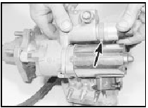
Position the plastic sleeve so that the drain hole faces the pump motor, then tighten the switch (see illustration).

19.4 Refit the pressure switch with the drain hole (arrowed) in the plastic
sleeve facing the pump motor - ABS
5 Reconnect the multi-plug and the battery.
6 On completion, bleed the complete hydraulic system and check for leaks around all disturbed components.
See also:
Mixture adjustment check (Every 6000 miles (10 000 km) or 6 months)
Caution: Refer to the
precautions in Section 1,
Chapter 4, Part A or B (as
applicable), before proceeding.
Before carrying out any carburettor
adjustments, ensure that the ignition
timing and sp ...
Handbrake - adjustment
1 Adjustment of the handbrake is normally
automatic by means of the self-adjusting
mechanism working on the rear brake shoes.
2 However, due to cable stretch, occasional
inspection of the handbrak ...
Brake drum - inspection and renewal
Note: Before starting work, refer to the note at
the beginning of Section 2 concerning the
dangers of asbestos dust.
1 Whenever a brake drum is removed, brush
out dust from it, taking care not to ...
