Bumper - removal and refitting
Front bumper
Models up to 1987
1 Remove the radiator grille panel.
2 Disconnect the battery negative lead, then disconnect the wiring plugs from the indicators, and where applicable the foglamps.
3 Working under the front wing, release the single bumper fastener from each side of the vehicle by turning the plastic clip through 90º (quarter of a turn).
4 On Ghia models, unclip the support strap between each front wing and the bumper.
5 Unscrew the single bolt securing each bumper fixing bracket to the body front panel, then pull the bumper forwards away from the body, disengaging the retaining pegs from the clips in each wing.
6 Refitting is a reversal of removal; ensure that all fixings are correctly located and secure.
Models from 1987
7 If foglamps are fitted, disconnect the
battery negative lead, then disconnect the
wiring plugs from the foglamps.
8 Working under the front wings, unscrew the single bolt from each side of the bumper.
9 Release the plastic retaining screws and pull the wheel arch liners away from the ends of the bumper.
10 Pull the bumper forwards away from the body, releasing the front mounting spigots from their sockets.
11 Refitting is a reversal of removal, but ensure that the reinforcing plate and O-ring are located on the right-hand mounting spigot.
12 The bumper height can be adjusted by turning the adjusters located on the front mounting spigots using a suitable Torx screwdriver with a length of at least 150.0 mm (6.0 in) (see illustrations).
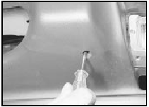
30.12a Adjusting the height of a front bumper - models from 1987
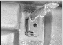
30.12b Front bumper height adjusting screw - models from 1987
Rear bumper - Saloon, Hatchback
and Estate models
13 Disconnect the battery negative lead, then
prise the number plate lamps from the bumper,
and disconnect the wiring plugs. Withdraw the
wiring through the bumper assembly.
14 Working inside the luggage compartment, unscrew the two bumper securing bolts.
15 Working under the rear wings, release the single bumper fastener from each side of the vehicle by turning the plastic clip through 90º (quarter of a turn) (see illustration).
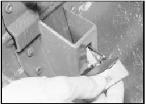
30.15 Rear bumper plastic fastener
16 Pull the bumper rearwards away from the body, disengaging the retaining pegs from the clips in each wing.
17 Refitting is a reversal of removal, but ensure that all fixings are correctly located and secure.
18 On some later models, the bumper height can be adjusted by means of the adjusters located on the mounting brackets - see paragraph 12 (see illustration).
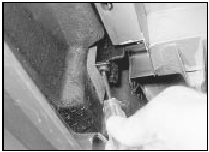
30.18 Adjusting the height of a rear bumper
Rear bump stop - P100 models 19 Working underneath the vehicle, unscrew the two securing nuts and washers from the bump stop studs, and withdraw the bump stop (see illustration).
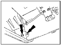
30.19 Rear bump stop securing nut locations (arrowed) - P100 models
20 Refitting is a reversal of removal.
Bumper trim moulding - renewal
New bumpers are supplied without the trim moulding fitted. Special primer and adhesive tape are specified by the manufacturer to retain the moulding: it is suggested that a Ford dealer is consulted for further details.
A damaged moulding can be removed by prising it from the bumper using a screwdriver.
See also:
Power steering gear - removal and refitting
Note: New power steering fluid hose O-rings
will be required when refitting.
Removal
1 The procedure is as described for manual
steering gear with the following differences
(see illustration).
...
Heating and ventilation system - description
The heater is of the type which utilises
waste heat from the engine coolant. The
coolant is pumped through the matrix in the
heater casing where air, force-fed by a duplex
radial fan, disperses th ...
Bosch K-Jetronic and KE-Jetronic mechanical fuel injection
systems
The fuel system comprises a centrally mounted fuel tank,
electrically-operated fuel pump and Bosch K-Jetronic or KE-Jetronic continuous
injection system according to model. The system is used in c ...
